


Philips Semiconductors Product specification
PDIUSBH12USB 2-port hub
1999 Jul 22
19
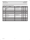
DC CHARACTERISTICS (Digital pins)
SYMBOL PARAMETER TEST CONDITIONS MIN TYP MAX UNIT
Input Levels
V
IL
LOW level input voltage 0.6 V
VIH
HIGH level input voltage 2.7 V
V
TLH
LOW to HIGH threshold voltage ST (Schmitt Trigger) pins 1.4 1.9 V
V
THL
HIGH to LOW threshold voltage ST pins 0.9 1.5 V
V
HYS
Hysteresis voltage ST pins 0.4 0.7 V
Output Levels
V
OL
LOW level out
p
ut voltage
I
OL
= rated drive 0.4
V
V
OL
LOW
level
out ut
voltage
I
OL
= 20 µA 0.1 V
V
OH
HIGH level out
p
ut voltage
I
OH
= rated drive 2.4
V
V
OH
HIGH
level
out ut
voltage
I
OH
= 20 µA V
CC
– 0.1 V
Leakage Current
I
OZ
OFF state current OD (Open Drain) pins ±1 µA
I
L
Input leakage current ±1 µA
I
S
Suspend current
Oscillator stopped and
inputs to GND/V
CC
15 µA
I
O
Operating current 02 ports operating 13 mA
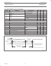
DC CHARACTERISTICS (AI/O pins)
SYMBOL PARAMETER TEST CONDITIONS MIN MAX UNIT
Leakage Current
I
LO
Hi-Z state data line leakage 0V < V
IN
< 3.3V ±10 µA
Input Levels
V
DI
Differential input sensitivity |(D+) – (D–)|
1
0.2 V
V
CM
Differential common mode range Includes V
DI
range 0.8 2.5 V
V
SE
Single-ended receiver threshold 0.8 2.0 V
Output Levels
V
OL
Static output LOW R
L
of 1.5kΩ to 3.6V 0.3 V
V
OH
Static output HIGH R
L
of 15kΩ to GND 2.8 3.6 V
Capacitance
C
IN
Transceiver capacitance Pin to GND 20 pF
Output Resistance
Z
DRV
2
Driver output resistance Steady state drive 28 43 Ω
Integrated Resistance
Z
PU
Pull-up resistance SoftConnect = ON 1.1 1.9 kΩ
Z
PD
Pull-down resistance Pull-down = ON 11 19 kΩ
NOTES:
1. D+ is the symbol for the USB positive data pin: UP_DP, DN2_DP, DN3_DP.
D– is the symbol for the USB negative data pin: UP_DM, DN2_DM, DN3_DM.
2. Includes external resistors of 22 W ± 1% each on D+ and D–.
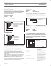
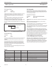
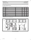
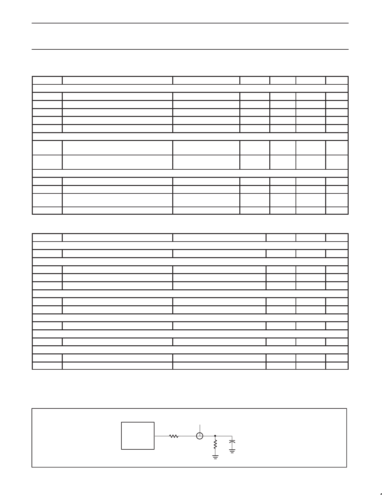
LOAD FOR D+/D–
D. U. T.
TEST POINT
C
L
= 50pF
1.5kΩ IS INTERNAL
15kΩ
22Ω
SV00849