


Philips Semiconductors Product specification
PDIUSBH12USB 2-port hub
1999 Jul 22
6
PINNING
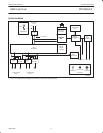
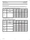
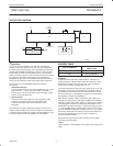
The PDIUSBH12 has two modes of operation. The first mode (Mode 0) configures the pins DNx_GL_N for GoodLink LED indication. The
second mode (Mode 1) configures the LED pins as per port overcurrent condition pins. An overcurrent condition on any port can be uniquely
identified in Mode 1. However, all downstream ports are disabled as a result of a single overcurrent condition. In addition to the two modes of
operation, the PDIUSBH12 can also be configured to take either a 48 MHz crystal oscillator (for backward compatibility to PDIUSBH11) or a 12
MHz crystal.
The internal 4X clock multiplier PLL will be activated when 12 MHz input XTAL mode is selected. Also, the output clock frequency is now
programmable rather than fixed to 12 MHz. The output clock frequency can be programmed through the Set Mode command. All these new
features are added while maintaining backward compatibility to the PDIUSBH11 through TEST2 and TEST1 pins.
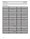
TEST2 TEST1
MODE
INPUT XTAL FREQUENCY
(MHz)
OUTPUT CLOCK FREQUENCY
(AT REST)
00
MODE 0
(GoodLink)
48 12MHz
01
MODE 0
(GoodLink)
12 4 MHz
10
MODE 1
(Individual Overcurrent)
12 4 MHz
11
MODE 1
(Individual Overcurrent)
48 12 MHz
NOTE:
1. Pin TEST3 should always be connected to Ground at all times.
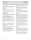
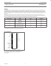
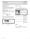
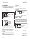
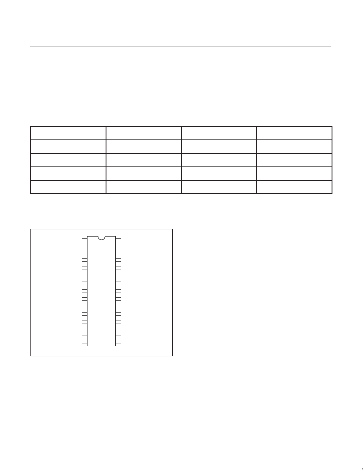
Pin configuration
1
2
3
4
5
6
7
8
9
10
11
12 17
18
19
20
21
22
23
24
25
26
27
28TEST1
TEST2
TEST3
RESET_N
GND
XTAL1
XTAL2
CLKOUT
V
CC
OCURRENT_N /
OCURRENT2_N
SWITCH_N
UP_DM
UP_DP
AV
CC
AGND
DN2_DM
DN2_DP
DN3_DM
GND
DN3_DP
SCL
SDA
INT_NSUSPEND
13 16 RSVDDN2_GL_N
14 15 RSVD
DN3_GL_N /
OCURRENT3_N
SV01751
NOTE:
Pin 10 and Pin 14 show alternative pin functions, depending on
mode of operation (Mode 0 or Mode 1) as described in
Pin Description
.