


ActivMedia Robotics
User Control Panel
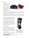
The User Control Panel is where you have access to the AROS-based onboard
microcontroller. Found inside the AT’s hinged access panel on the deck or on the left-
side panel of the DX, it consists of control buttons and indicators, and an RS232-
compatible serial port with a 9-pin DSUB connector.
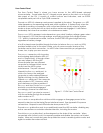
The red PWR LED is lit whenever main power is applied to the robot. The green STAT LED
state depends on the operating mode and other conditions. It flashes slowly when the
controller is awaiting a connection with a client and flashes quickly when in joydrive
mode or when connected with a client and the motors are engaged. It also flashes
moderately fast when the controller is in maintenance mode.
The BATTERY LED’s apparent color depends on your robot’s battery voltage: green when
fully charged (>12.5 volts) through orange, and finally red when the voltage is below
11.5. When in maintenance mode, however, the BATTERY LED glows bright red only,
regardless of battery charge.
A built-in piezo buzzer (audible through the holes just above the STAT and PWR LEDs)
provides audible clues to the robot’s state, such as upon successful startup of the
controller and a client connection. An AROS client command lets you program the
buzzer, too, to play your own sounds.
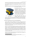
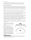
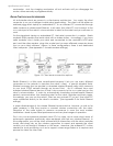
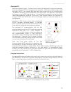
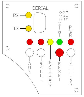
Figure 11. P3-DX User Control Panel
The SERIAL connector, with incoming
and outgoing data indicator LEDs (RX
and TX, respectively), is through where
you may interact with the H8S
microcontroller from an offboard
computer for tethered client-server
control and for AROS system
maintenance. The port is shared
internally by the HOST serial port, to
which we connect the onboard
computer or radio modem/Ethernet.
Digital switching circuitry disables the
internal HOST serial port if the computer
or
radio modem is OFF. However, serial
port interference will be a problem if
the HOST and User Control SERIAL ports
are both occupied and engaged.
Accordingly, remove the cable from
the SERIAL port if you plan to connect
with the controller through the onboard
radio modem or PC.
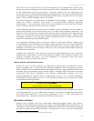
RADIO and AUX are pushbutton switches which engage or disengage power to the
respective devices on the Motor/Power Interface board. See Appendix B for power
connections. Respective red LEDs indicate when power is ON.
The red RESET pushbutton acts to unconditionally reset the H8S controller, disabling any
active connections or controller-attached devices, including the motors.
The white MOTORS pushbutton’s actions depend on the state of the controller. When
connected with a client, push it to manually enable and disable the motors, as its label
implies. When not connected, press the pushbutton once to enable joydrive mode, and
again to enable the motors self-test.
13