


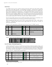
Appendix B: Motor-Power Board Connectors
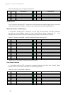
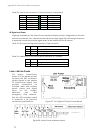
Table 32. User Power connector (12-pos latchlock; unswitched)
PIN CONNECTION PIN CONNECTION
1
Vcc
7
Vcc
2
Gnd
8
Gnd
3
Vpp
9
Vpp
4
Vcc
10
Vcc
5
Gnd
11
Gnd
6
Vpp
12
Vpp
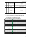
IR Signal and Power
Originally available on the Motor-Power Interface Board and now integrated on the new
Motor-Power board, four connectors provide power and signal for fixed-range IR sensors.
A separate connector provides signal path for an additional four IR sensors.
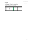
Table 33. IR power and signal connectors (3-pos microfits)
PIN SIGNAL DESCRIPTION
1
Vpp Battery 12 VDC
2
IRn Switching signal
3
Gnd Power/signal ground
Table 34. Additional IR connector (8-pos latchlock 0.1 header)
PIN SIGNAL DESCRIPTION
1-4
IR4-7 IR signals
5-8
GND Signal common
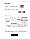
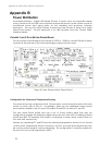
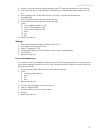
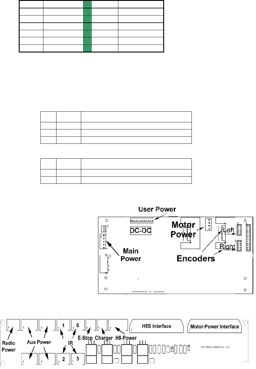
LEGACY MOTOR-POWER
Figure 27. The Original P2 Motor-Power Board
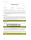
The legacy Motor-Power
system is a two-board set that
connects the H8S controller’s
control signals to the original
P2 Motor-Power board, and
provides connections for
switched radio and auxiliary
power, power and digital
inputs for IRs, charge-
detection port, and
emergency stop detector.
See the H8S-controller board
in Appendix A for interface
connection specifications.
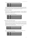
Figure 28. Motor-Power interface board
72