


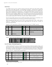
Appendix B: Motor-Power Board Connectors
Appendix B
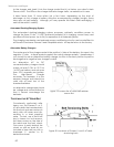
Power Distribution
ActivMedia Robotics’ original H8S-based Pioneer 2 robots have two separate boards
which interface with the H8S microcontroller and provide power for the motors as well as
conditioned power and signal paths for the standard and accessory onboard
electronics. The new Plus-series Pioneer 2 robots and the Pioneer 3s have just a single
Motor-Power Board. Consult Appendix A for H8S-controller and User Control Panel
interface details.
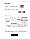
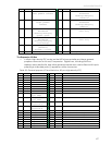
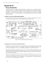
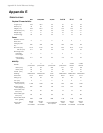
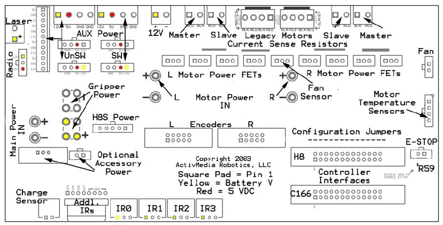
PIONEER 3 AND 2-PLUS MOTOR-POWER BOARD
The new Motor-Power Board for the Pioneer 2-AT8 Plus, –DX8 Plus, and all Pioneer 3 robots
contains all the features of the two-board legacy system and lots more.
Figure 26. New Pioneer Motor-Power Board
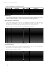
Configuration for Current and Temperature Sensing
The motor drivers are configured to limit 10A per motor, and to share the drivers with both
motors on each side of the AT. Accordingly, there are two additional motor-current
sense resistors added to the AT versus DX board: R3 and R26, as well as R1 and R2.
The new Motor-Power board also has a set of 0-ohm resistor pads that may be
configured to engage the analog-to-digital input ports AN1 and AN2. By adding jumpers
to R60 and R62, for example, the board is configured to sense motor current draw on
AN1 and AN2, respectively.
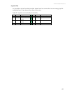
Instead, by jumpering R77 and R78 and by attaching temperature sensors to two motors
via the Motor Temperature Sensors connector, the AN1 and AN2 ports respectively may
be used to protect against motor overheating. This configuration is currently enabled in
the new ATs, but not yet supported in AROS.
70