


ActivMedia Robotics
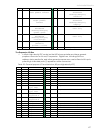
Table 28. Motor Temperature Sensors Connector (4-pos microfit)
PIN SIGNAL DESCRIPTION
1
Vcc 5 VDC
2
T2 To AN2-based temp sensor circuit
3
T1 To AN1-based temp sensor circuit
4
GND Signal/power common
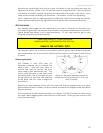
Otherwise, a jumper across R76 connects the AN1 port to the Fan Sensor system that is
attached to the FET heat sink. Note, too, that with or without attachment of AN1 via R76,
but with the heat sensor in place, a fan may be attached and activated whenever the
motor-driver FETs get overheated, as implemented in all new AT systems.
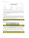
Controller Power and Interface
Individual 26-pos IDC connectors and cables provide signal for the new H8S-based
microcontroller or the legacy C166-based microcontrollers. A separate cable and
connector provides for the H8S microcontroller and sonar power. Power and signal are
shared on the C166 controller connector.
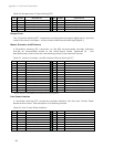
Table 29. H8S Power connector (5-pos microfit)
PIN SIGNAL DESCRIPTION
1
Vbat Battery power
2
Gnd Power common
3
Vcc 5 VDC for sonar
4
Vcc 5 VDC for sonar
5
nc No connection
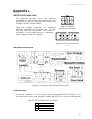
Radio, Auxiliary, and User Power Connectors
Various connectors provide conditioned 5 VDC @ 1.5A total and unconditioned battery
power for the variety of accessories and custom user attachments. Some are AUX and
RADIO power switched from the User Control Panel. And some are for Use the 12-position
latchlock connector for legacy installations. Otherwise, screw-down auxiliary user-power
connectors make custom attachments easy. Four-position microfit connectors also
provide AUX power for standard accessories.
Table 30. User Control Panel-switched radio power connector (3-pos microfit)
PIN SIGNAL DESCRIPTION
1
Vpp Radio switched battery 12 VDC
2
Gnd Power common
3
Vcc Radio switched 5 VDC
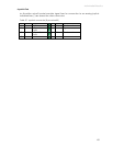
Table 31. User Control Panel-switched and unswitched Aux power connectors (4-pos
microfits and screw-down terminal blocks)
PIN SIGNAL DESCRIPTION
1
Vpp Aux switched battery 12 VDC
2
Vcc Aux switched 5 VDC
3
Gnd Power common
4
Gnd Power common
71