


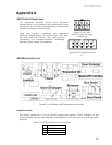
Appendix A: Ports and Connections
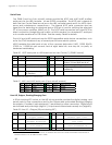
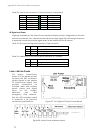
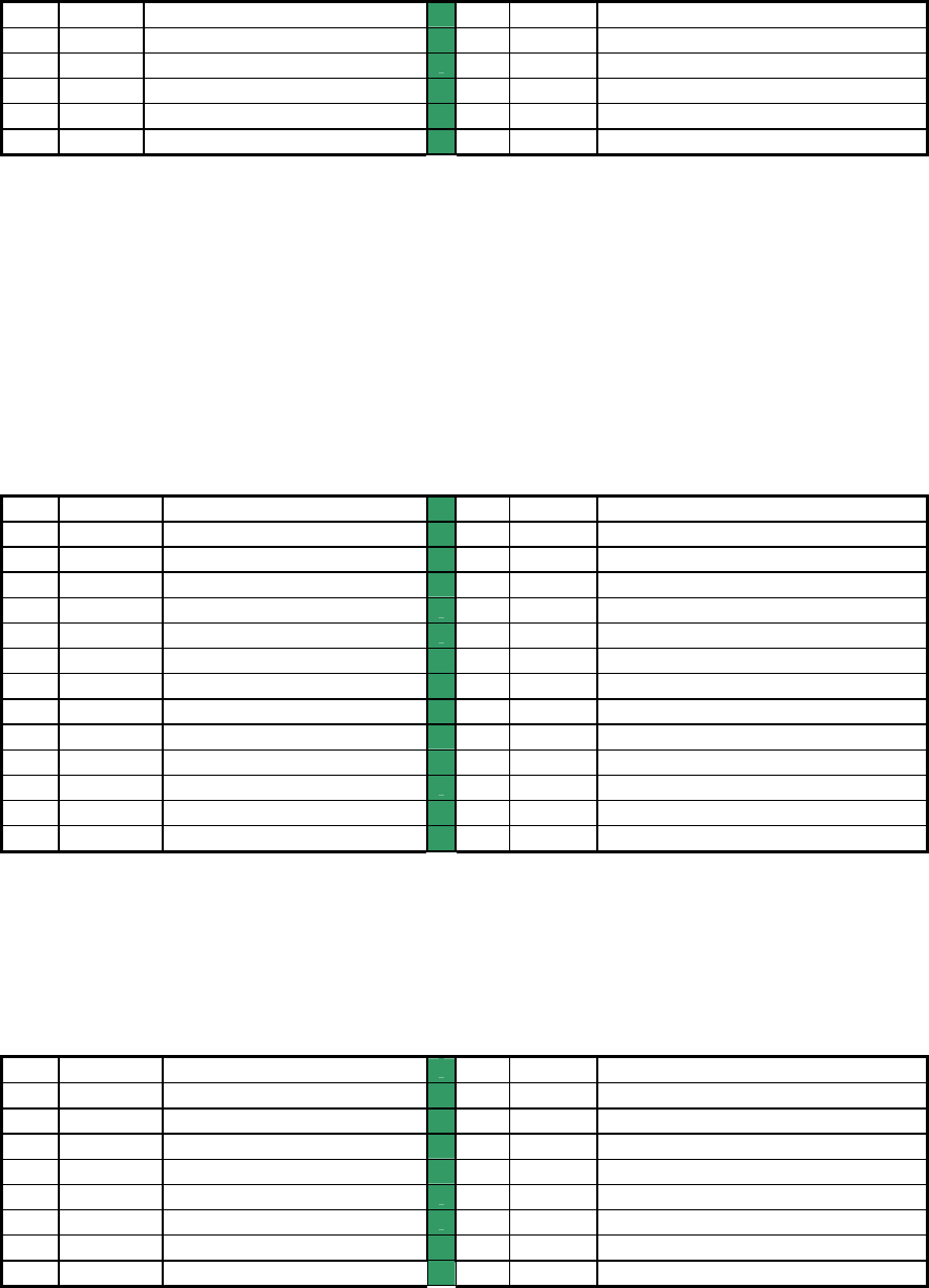
Table 24. Bumper ports (10-pos latching IDC)
PIN SIGNAL DESCRIPTION
PIN SIGNAL DESCRIPTION
1
BP0 Bumper bit 0
2
BP1 Bumper bit 1
3
BP2 Bumper bit 2
4
BP3 Bumper bit 3
5
BP4 Bumper bit 4
6
BP5 Bumper bit 5
7
BP6 Bumper bit 6
8
BP7 Bumper bit 7
9
Gnd Common
10
Gnd Common
Bumper Ports
Two 10-position latching IDC connectors provide general-purpose digital inputs, typically
used for the robot’s bumpers. All inputs are buffered and pulled high (digital 1).
Motors, Encoders, and IR Sensors
A 26-position latching IDC connector on the H8S microcontroller provides interface
through an intermediate board to the Motor-Power Board (Appendix B). Line
descriptions also can be found in the following Motor-Power Interface section.
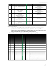
Table 25. Motors, encoders, and IRs interface (26-pos latching IDC)
PIN SIGNAL DESCRIPTION
PIN SIGNAL DESCRIPTION
1
LPWM Left motors PWM
2
LDIR Left motors direction
3
RPWM Right motors PWM
4
RDIR Right motors direction
5
MEN Motors enable
6
LEA Left encoder channel A
7
E-STOP E-Stop detect input
8
REA Right encoder channel A
9
RPWR Radio power enable
10
REB Right encoder channel B
11
APWR Aux power enable
12
LEB Left encoder channel B
13
CHRG Charge port detect
14
IR6 IR input bit 6
15
IR7 IR input bit 7
16
IR4 IR input bit 4
17
IR5 IR input bit 5
18
IR2 IR input bit 2
19
IR3 IR input bit 3
20
IR0 IR input bit 0
21
IR1 IR input bit 1
22
VBAT Battery voltage detect
23
Gnd Signal common
24
AN1* Analog input
25
Gnd Signal common
26
AN2* Analog input
* Board versions C and earlier pin 24 HOST RI and pin 26 ground.
User Control Interface
A 16-position latching IDC connector provides interface with the User Control Panel
board and functions. See description in a following section.
Table 26. User Control Panel interface
PIN SIGNAL DESCRIPTION
PIN SIGNAL DESCRIPTION
1
Vcc 5 VDC power
2
Vcc 5 VDC power
3
RST RESET button
4
MOT MOTORS button
5
RPWR Radio power switch
6
APWR Aux power switch
7
CHRG Charging indicator
8
BZR Buzzer PWM
9
PLED Main power
10
SLED Status
11
Vpp Battery 12 VDC
12
Gnd Signal/power common
13
Gnd Signal/power common
14
HTXD HOST serial transmit
15
HDSR HOST serial enabled
16
HRCV HOST serial receive
68