


ActivMedia Robotics
ONBOARD PC
Unlike the original Pioneer 1, Pioneer 2 and 3 robots are designed to support an onboard,
internally integrated PC for fully autonomous operation. Mounted just behind the nose of
the robot, the PC is a common EBX form-factor that comes with up to four serial ports,
10/100Base-T Ethernet, monitor, keyboard, and mouse ports, two USB ports, and support
for floppy, as well as IDE hard-disk drives. For additional functionality, such as for sound,
video framegrabbing, firewire or PCMCIA bus, and wireless Ethernet, the onboard PC
accepts PC104 and PC104-plus (PCI bus-enabled) interface cards that stack on the
motherboard.
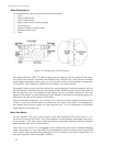
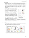
Necessary 5 VDC power comes from a dedicated
DC:DC converter, mounted nearby. A hard-disk
drive is specially shock-mounted to the robot’s nose,
in between a cooling fan and computer speaker.
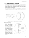
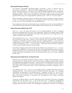
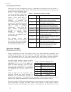
Figure 14. DX computer
control side panel
The onboard PC communicates with the H8S
microcontroller through its HOST serial port and the
dedicated serial port COM1 under Windows or
/dev/ttyS0 on Linux systems. Automatic systems on
the microcontroller switch in that HOST-to-PC
connection when PC-based client software opens
the serial port. Otherwise, the PC doesn’t interfere
with externally connected clients through the shared
SERIAL port on the User Control Panel.
Note also that some signals on the H8S
microcontroller’s HOST serial port as connected with
the onboard PC or other accessory can be used for
automated PC shutdown or other utilities: Pin 4 (DSR) normally is RS232 high when the
controller operates normally; otherwise it is low when reset or in maintenance mode.
Similarly, pin 9 (RI) normally is low and goes RS232-level high when the robot’s batteries
drop below a set (nominally 11 VDC) voltage level.
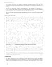
Computer Control Panel
User-accessible communication and control port connectors, switches, and indicators for
the onboard PC are on the Computer Control Panel, found on the right side panel of the
DX or in the hinged control well next to the User Controls of the AT.
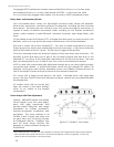
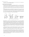
Figure
15
. AT computer and user controls
19