


ActivMedia Robotics Operating System
At the same time, AROS reports back to the client in the standard SIP the robot’s position
and speed. Not all robots convert these values into platform-independent units. ARIA
and Saphira clients rely on conversion factors found in your robot’s respective “.p”
parameter file to make the necessary conversion.
So when you tell the robot to move a certain number of millimeters forward, measure its
actual travel with a meter tape and adjust ticksmm accordingly. Similarly, turn the robot
and adjust revcount to achieve the correct heading.
Then, when you are satisfied that the robot moves and turns precisely, adjust the various
parameter file-based conversion factors, such as DistConvFactor, so that the client
reports the robot’s position and speeds in platform-independent units.
Please see the next chapter for a detailed description of these platform-dependent
variables.
PID Controls
The AROS drive servers use a common Proportional-Integral-Derivative (PID) control
system to adjust the PWM pulse width at the motor drivers and subsequent power to the
motors. The motor-duty cycle is 200 microseconds; pulse-width is proportional 0-500 for 0-
100% of the duty cycle.
The AROS drive servers recalculate and adjust your robot’s trajectory and speed every
five milliseconds based on feedback from the wheel encoders.
The default PID values for translation and
rotation and maximum PWM are stored
as FLASH parameters in your robot’s H8S
microcontroller and may be changed.
You also may temporarily update the PID
values with the AROS client commands
#84 through #87. On-the-fly changes
persist until the controller is reset. The
translational PID values apply to
independent wheel-velocity mode.
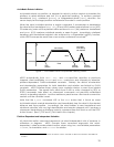
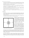
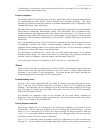
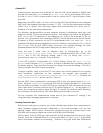
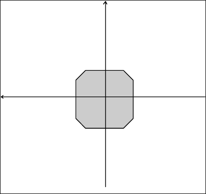
0
+90
+180
+270
+X
+Y
Front
Figure 18. Internal coordinate system
The P term value Kp increases the overall
gain of the system by amplifying the
position error. Large gains will have a
tendency to overshoot the velocity goal;
small gains will limit the overshoot but
cause the system to become sluggish.
We’ve found that a fully loaded robot
works best with a Kp setting of around 15
to 20, whereas a lightly loaded robot may
work best with Kp in the range of 20 to 30.
The D term Kv provides a PID gain factor that is proportional to the output velocity. It has
the greatest effect on system damping and minimizing oscillations within the drive
system. The term usually is the first to be adjusted if you encounter unsatisfactory drive
response. Typically, we find Kv to work best in the range of 600 to 800 for lightly to heavily
loaded robots, respectively.
The I Term Ki moderates any steady state errors thereby limiting velocity fluctuations
during the course of a move. At rest, your robot will seek to “zero out” any command
position error. Too large of a Ki factor will cause an excessive windup of the motor when
the load changes, such as when climbing over a bump or accelerating to a new speed.
40