


Appendix A: Ports and Connections
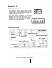
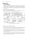
Serial Ports
Two DSUB-9 and two 5-pin microfit sockets provide the HOST and AUX1/AUX2 auxiliary
serial ports for the H8S controller. All are RS-232 compatible. The HOST port is shared on
both the User Control Panel as well as on the H8S controller board and is for AROS client-
server and maintenance connections.
26
The internal HOST serial connector also has
signal lines for detecting an attached device (DTR pin 4) and for notifying the attached
PC of low-power condition (HRNG pin 9). The HOST serial connectors are wired DCE for
direct connection (straight-through cable, not NULL-modem) to a standard PC serial port
or to a radio modem set to DTE mode. See the nearby Tables for details.
The AUX1 and AUX2 serial ports are for RS232-compatible serial device connections, such
as for the TCM2 Modules or any of several pan-tilt-zoom robotic systems.
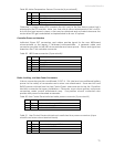
AROS operates the serial ports at any of the common data rates: 9,600, 19,200, 38,400,
57,800, or 115,200 bits per second; and at eight data bits, one stop bit, no parity or
hardware handshaking.
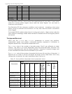
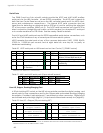
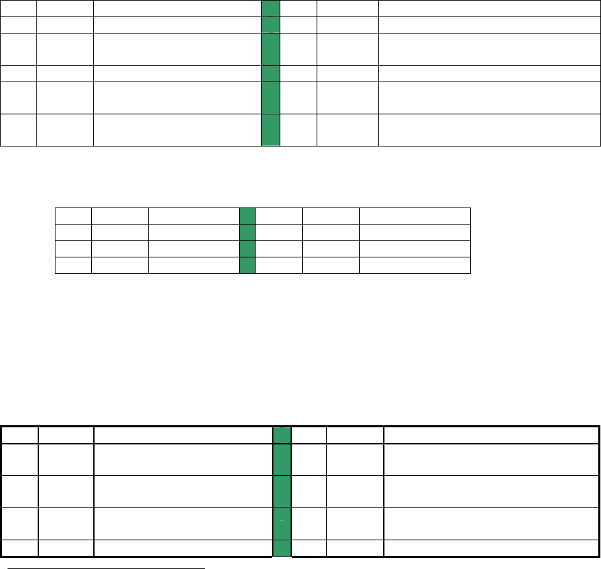
Table 20. HOST serial ports on H8S board and on User Control (*) (DSUB-9 socket)
PIN SIGNAL DESCRIPTION PIN SIGNAL DESCRIPTION
1
nc
2
*TXD output
3
*RCV Input
4
DTR Input detects attached device and
switches TxD and RxD into the uC
5
*GND Common
6
*DSR Output when controller powered
7
nc May be jumpered to pin 8
8
nc Jumper to pin 7 for radio modem
handshaking
9
†
RI Output lowered to signal
PC shutdown
†
Shared on Motors interface
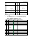
Table 21. AUX1 and AUX2 serial ports (5-pos microfit sockets)
PIN SIGNAL DESCRIPTION PIN SIGNAL DESCRIPTION
1
DTR Input
2
TXD output
3
RCV Input
4
DSR output
5
GND common
User I/O, Gripper, Docking/Charging Port
A 20-pin latching IDC socket on the H8S microcontroller provides the digital, analog, and
power ports for user connections and for the Gripper and automated docking/charging
accessories, if installed. Indicated ports (*) are shared on other connectors. Digital inputs
are buffered and pulled high (digital 1); outputs are buffered and normally low (digital 0).
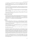
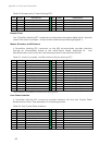
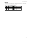
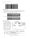
Table 22. User I/O – Gripper (20-pos latching IDC)
PIN SIGNAL DESCRIPTION
PIN SIGNAL DESCRIPTION
1
OD0 DIGOUT bit 0;
Gripper enable
2
ID0 DIGIN bit 0;
Paddles open limit
3
OD1 DIGOUT bit 1;
Gripper direction
4
ID1 DIGIN bit 1;
Lift limit
5
OD2 DIGOUT bit 2;
Lift enable
6
ID2 DIGIN bit 2;
Outer breakbeam IR
7
OD3 DIGOUT bit 3;
8
ID3 DIGIN bit 3;
26
Unlike with earlier P2 controllers, HOST does not interfere with the User Control Panel serial connections if its
attached device—PC or radio modem—is OFF.
66