


ActivMedia Robotics
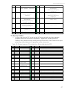
Lift direction Inner breakbeam IR
9
ID4 DIGIN bit 4;
Left paddle contact
10
OD4 DIGOUT bit 4;
Automated
docking/charging
“inhibit”
11
ID5 DIGIN bit 5;
Right paddle
contact
12
OD5 DIGOUT bit 5;
Automated
docking/charging
“deploy”
13
ID6 DIGIN bit 6;
Automated
docking/charging
”power good”
14
OD6 DIGOUT bit 6;
User only
15
ID7 DIGIN bit 7;
Automated
docking/charging
”overcharge”
16
OD7 DIGOUT bit 7;
User only
17
*AN0 A/D port 0
(default)
(0-5VDC = 0-255)
18
Vcc 5VDC < 1A
19
Vpp Battery 12VDC < 1A
20
Gnd Signal/power common
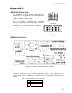
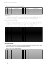
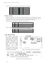
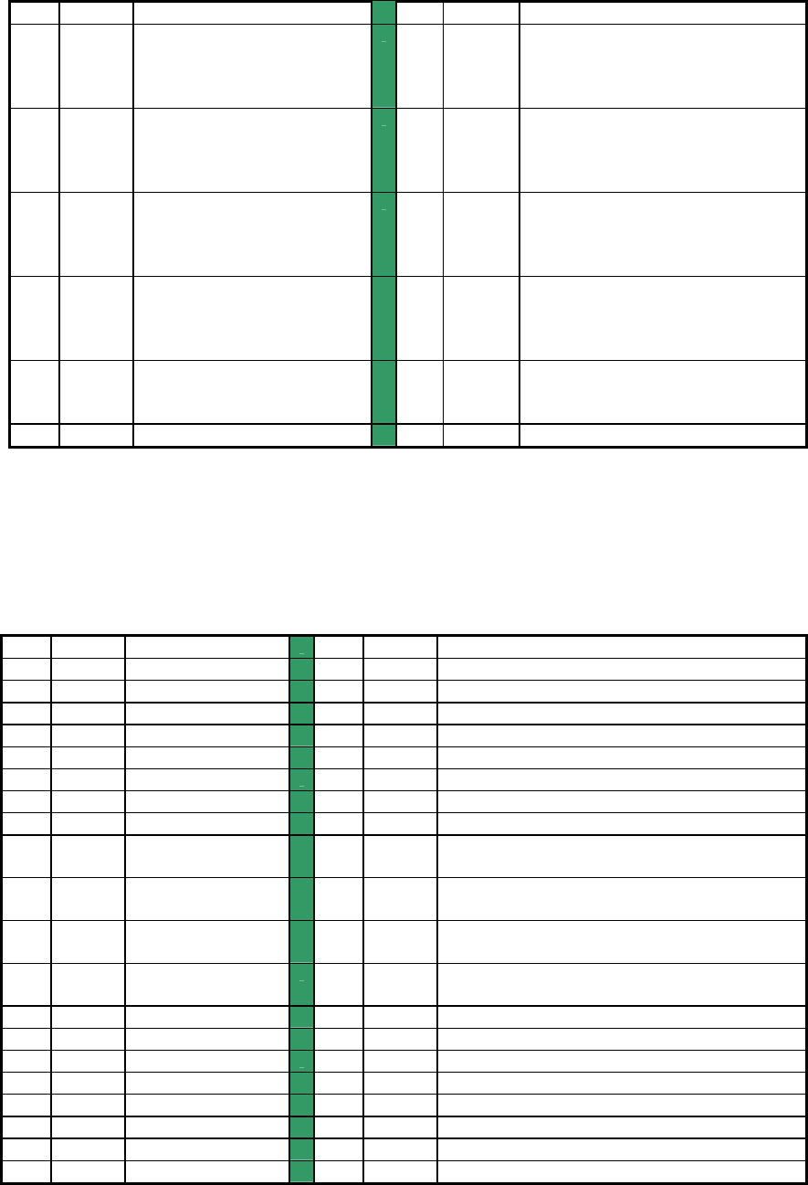
The Expansion I/O Bus
A 40-pin high-density IDC socket on the H8S microcontroller provides a general-
purpose connector for future I/O expansion. Digital lines, including 8-bit bus
address, data, read/write, and other general-purpose ones, are buffered with inputs
pulled high. Indicated ports (*) appear on other connectors.
Table 23. General-purpose I/O and data bus (40-pos high-density IDC)
PIN SIGNAL DESCRIPTION
PIN SIGNAL DESCRIPTION
1
AD0 Address bit 0
2
D7 Data bit 7
3
AD1 Address bit 1
4
D6 Data bit 6
5
AD2 Address bit 2
6
D5 Data bit 5
7
AD3 Address bit 3
8
D4 Data bit 4
9
AD4 Address bit 4
10
D3 Data bit 3
11
AD5 Address bit 5
12
D2 Data bit 2
13
ID6 Address bit 6
14
D1 Data bit 1
15
ID7 Address bit 7
16
D0 Data bit 0
17
AN6 A/D port 6;
gyro temp
18
CS4 Chip select 4
19
AN5 A/D port 5;
gyro rate
20
CS3 Chip select 3
21
*AN4 A/D port 4;
Joystick Y
22
CS2 Chip select 2
23
*AN3 A/D port 3;
Joystick X
24
WR Data write
25
AN2 A/D port 2
26
RD Data read
27
AN1 A/D port 1
28
CS6 Chip select 6 or digital I/O
29
*AN0 A/D port 0
30
CS7 Chip select 6 or digital I/O
31
GND Signal common
32
RST Controller reset
33
GND Signal common
34
P1.1 Digital I/O
35
GND Signal common
36
Vcc Controller 5VDC (<200ma)
37
GND Signal common
38
Vcc Controller 5VDC (<200ma)
39
GND Signal common
40
Vpp Battery 12VDC (<0.5A)
67