


APPENDEX A
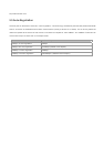
A.1 Switch's RJ-45 Pin Assignments
1000Mbps, 1000Base T
Contact MDI MDI-X
1 BI_DA+ BI_DB+
2 BI_DA- BI_DB-
3 BI_DB+ BI_DA+
4 BI_DC+ BI_DD+
5 BI_DC- BI_DD-
6 BI_DB- BI_DA-
7 BI_DD+ BI_DC+
8 BI_DD- BI_DC-
Implicit implementation of the crossover function within a twisted-pair cable, or at a wiring panel, while not expressly forbidden,
is beyond the scope of this standard.
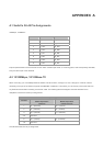
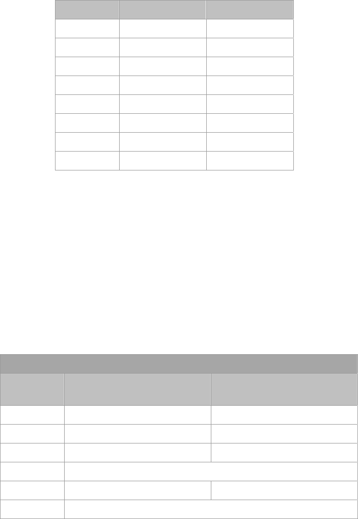
A.2 10/100Mbps, 10/100Base-TX
When connecting your 10/100Mbps Ethernet Switch to another switch, a bridge or a hub, a straight or crossover cable is
necessary. Each port of the Switch supports auto-MDI/MDI-X detection. That means you can directly connect the Switch to
any Ethernet devices without making a crossover cable. The following table and diagram show the standard RJ-45
receptacle/ connector and their pin assignments:
RJ-45 Connector pin assignment
Contact
MDI
Media Dependant
Interface
MDI-X
Media Dependant
Interface-Cross
1 Tx + (transmit) Rx + (receive)
2 Tx - (transmit) Rx - (receive)
3 Rx + (receive) Tx + (transmit)
4, 5 Not used
6 Rx - (receive) Tx - (transmit)
7, 8 Not used
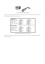
The standard cable, RJ-45 pin assignment