


User’s Manual of SGSD-1022 / SGSD-1022P
SGSW-2840 / SGSW-2840P
677
References:
IEEE Std 802.3af-2003 (Amendment to IEEE Std 802.3-2002, including IEEE Std 802.3ae-2002), 2003 Page(s):0_1-121
White Paper on Power over Ethernet (IEEE802.3af)
http://www.poweroverethernet.com/articles.php?article_id=52
Microsemi /PowerDsine
http://www.microsemi.com/PowerDsine/
Linear Tech
http://www.linear.com/
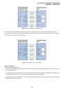
The PoE Provision Process
While adding PoE support to networked devices is relatively painless, it should be realized that power cannot simply be
transferred over existing CAT-5 cables. Without proper preparation, doing so may result in damage to devices that are not
designed to support provision of power over their network interfaces.
The PSE is the manager of the PoE process. In the beginning, only small voltage level is induced on the port's output, till a valid
PD is detected during the Detection period. The PSE may choose to perform classification, to estimate the amount of power to
be consumed by this PD. After a time-controlled start-up, the PSE begins supplying the 48 VDC level to the PD, till it is
physically or electrically disconnected. Upon disconnection, voltage and power shut down.
Since the PSE is responsible for the PoE process timing, it is the one generating the probing signals prior to operating the PD
and monitoring the various scenarios that may occur during operation.
All probing is done using voltage induction and current measurement in return.
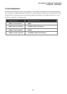
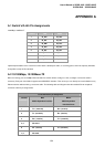
Stages of powering up a PoE link
Stage Action
Volts specified
per 802.3af
Volts managed
by chipset
Detection
Measure whether powered device has the correct signature
resistance of 15–33 kΩ
2.7-10.0 1.8–10.0
Classification
Measure which power level class the resistor indicates 14.5-20.5 12.5–25.0
Startup
Where the powered device will startup >42 >38
Normal operation
Supply power to device 36-57 25.0–60.0
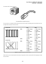
Line Detection
Before power is applied, safety dictates that it must first be ensured that a valid PD is connected to the PSE's output. This
process is referred to as "line detection", and involves the PSE seeking a specific, 25 KΩ signature resistor. Detection of this
signature indicates that a valid PD is connected, and that provision of power to the device may commence.