


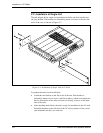

Installation in 19" Racks
C-4 ASMi-450 Installation and Operation Manual
• Fasten one short adapter bracket to the left-hand side wall of the unit
intended to be on the left. Use two of the four longer screws supplied in the
kit, and insert flat washers.
• Use the same procedure to fasten the second short adapter to the right-hand
wall of the unit intended to be on the right.
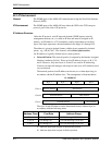
• Position one of the two rails supplied in the kit on the right-hand wall of the
unit intended to be on the left, and align its holes with the holes on the wall.
• Insert four short Philips screws and screw them through the rail into the
holes on the unit wall.
• Use the same procedure to attach the second rail to the left-hand wall of the
unit intended to on the right. Make sure the wider rim of this rail is opposite
the short rim of the other rail, as shown in figure C-2.
Fastening the Two
Units
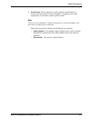
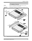
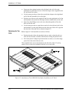
Refer to figure C-3 and attach the two units as follows:
• Position the ends of the rails attached to the two units so that the rails can
slide one into the other, and then slide the units to bring the panels in line.
• Now insert plastic I-shaped caps between the two units, to cover the empty
spaces left at the ends of the two rails.
The assembled units can now be fastened to the side rails of the 19" rack by
means of four screws (not included in the kit), two on each side.
Figure C-3. Attachment of Two ASMi-450 Units Before Installation in 19" Rack