


ASMi-450 Control from the Control Port
4-16 ASMi-450 Installation and Operation Manual
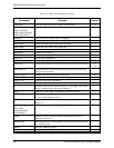
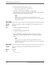
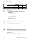
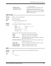
Terminal Type
TV- 920 VT-52 VT-100 Freedom-110 Freedom-220
Clear Screen 1B2A0000 N/A 1B5B324A 1B2A0000 1B5B324A
Cursor Home 1E000000 1B480000 1B5B4800 1E000000 1B5B4800
Cursor Right 0C000000 1B430000 1B5B3143 0C000000 1B5B0143
Format
DEF TERM 'terminal'
Use
1. To configure the ASMi-450 for using the control sequences corresponding to a
supported terminal, type:
DEF TERM 'terminal'<CR>
where 'terminal' stands for one of the types listed in the table above.
2. In response, you will see the new control sequences, in the format shown below:
New Control Sequences:
CLEAR SCREEN = hhhhhhhh
CURSOR HOME = hhhhhhhh
CURSOR RIGHT = hhhhhhhh
where
h
indicates hexadecimal digits.
DSP ALM--------------------------------------------------------------------------------------
Purpose
Display the contents of the alarm buffer. This buffer can contain up to 100 alarms.
Format
DSP ALM [Option]
Use
1. To display the complete contents of the buffer, type:
DSP ALM<CR>
2. To display the complete buffer contents and then clear the type-ON alarms, type:
DSP ALM /C<CR>
3. To display the complete buffer and then clear all the stored alarms, type:
DSP ALM /CA<CR>
Display
Format
The contents of the alarm buffer are displayed as a table with four columns: the alarm
number and alarm syntax (description), alarm state, and time of alarm occurrence. Each
block of alarms received from a ASMi-450 is preceded by a header. The header lists the
assigned node name and the node number of the ASMi-450 unit which sent the alarm
block, and thus it serves as an easily-identified separator between alarms transmitted by
different ASMi-450 units.
Table 4-2 lists all the alarm messages that can be displayed by the terminal.
Function