


Front-Panel Operating Instructions
ASMi-450 Installation and Operation Manual 3-5
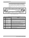
Status Messages
When the ASMi-450 is not being configured and no test is active, its display
shows status messages. The alarm buffer can store up to 100 alarms. The
presence of status messages in the alarm buffer is indicated by the ALM
indicator.
The status messages appear under the header ALARM BUFFER. The status
messages are described in Chapter 5.
Test Functions
The test functions include:
• Local and remote loopbacks on the user's port, for rapid isolation of faults.
• BER test (future option).
Note
Do not activate any loopback when using an ASMi-450 with Ethernet interface.
The test function messages appear under the header TEST OPTIONS.
Chapter 5 describes the available test functions.
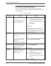
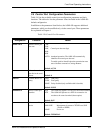
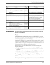
Configuration Parameters
The ASMi-450 has two groups of configuration parameters:
• System parameters.
• Control port parameters.
The configuration parameter groups are detailed in the following chart.
Display Description See...
SYSTEM PARAMETER Display and selection of system parameters:
- Master clock source
- Selection of active time slots
Sec. 3-4
SP PARAMETER Display and selection of ASMi-450 control port parameters:
- Data rate
- Number of data bits
- Parity
- Interface type
Sec. 3-5
In addition to the parameters configured from the front panel, there are
parameters that can be controlled only via the control port. These are presented
in Chapter 4.
After configuration, if alarm messages are stored in its ALARM BUFFER and
no test is active, the ASMi-450 automatically returns to the display of alarm
messages.