


Front-Panel Operating Instructions
ASMi-450 Installation and Operation Manual 3-15
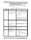
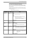
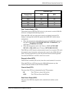
Step Action Key Display
9 After completing the configuration actions,
you can use steps 1, 2 to return to the
ALARM BUFFER.
If alarm messages are stored in the alarm
buffer, ALARM BUFFER will be
automatically displayed if no push-button is
pressed for one minute.
SCROLL The top row shows:
ALARM BUFFER
Specific
Configuration
Guidelines
This section presents specific configuration guidelines for the selection of
parameter values. You may also wish to refer to Section 1-2, that provides a
concise description of the ASMi-450 operating environment, including
explanations for many of the relevant terms.
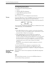
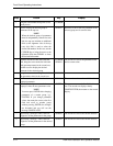
SYSTEM PARAMETER
See parameter definitions in Section 3-4.
CLK MASTER
The selection can be made only at the unit configured as
CNTR.
•
For connection to carrier lines, select EXT.
•
For a point-to-point application with stand-alone
equipment at both link ends, you can also select INT.
•
For ASMi-450 with Ethernet interface, select INT.
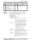
ACTIVE TS •
For ASMi-450 models with DCE interface, the
number of active time slots must be equal to the
multiplier of the basic data rate (64 kbps) which
yields the required user's data rate. The maximum
number of active time slots depends on the
ASMi-450 model:
5
ASMi-450/768: 12 time slots
5
ASMi-450/1152: 18 time slots
ETHERNET Select the method used to handle the LAN traffic,
MODE half-duplex (HALF_DUP) or full-duplex (FULL_DUP).
This parameter appears only for ASMi-450 version with
the Ethernet interface.
BRIDGING Select FILTERED if you want to operate the E1 link as a
remote bridge (the recommended method). To operate the
link as a LAN extender (or repeater), select TRAN.
This parameter appears only for ASMi-450 version with
the Ethernet interface.