


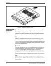

Installation
2-8 ASMi-450 Installation and Operation Manual
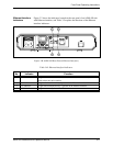
2.5 Connections
Connector
Location
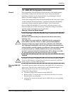
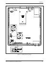
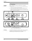
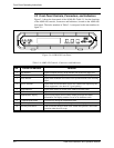
Figure 2-3 shows typical rear panels of ASMi-450 units, and identifies
connector locations:
• Figure 2-3.A shows the rear panel of an AC-powered ASMi-450 unit (the
unit shown in this figure has an RS-530 interface).
• Figure 2-3.B shows the rear panel of a DC-powered ASMi-450 unit (the
unit shown in this figure has an Ethernet interface; for an explanation of the
indicator functions, refer to Chapter 3).
A. Typical AC Powered Unit
B. Typical DC-Powered Unit
Figure
2-3
. Typical ASMi-450 Rear Panels
Grounding
Any interruption of the protective (grounding) conductor (inside or outside the
instrument) or disconnecting the protective earth terminal can make this
instrument dangerous. Intentional interruption is prohibited.