


Introduction
1-2 ASMi-450 Installation and Operation Manual
• Ethernet 10BaseT interface. The interface can use unshielded and shielded
twisted pair (UTP and STP) media. The ASMi-450 also includes a remote
bridge, that can be enabled/disabled by the user.
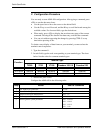
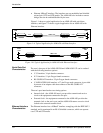
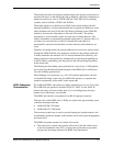
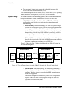
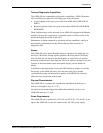
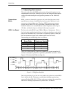
Figure 1-1 shows a typical application for an ASMi-450 with serial data
interface, and figure 1-2 shows a typical application for an ASMi-450 with
Ethernet interface.
Figure 1-A. Typical Application for ASMi-450 with Data Interface
Figure 1-B. Typical Application for ASMi-450 with Ethernet Interface
Serial Data Port
Characteristics
The user's data port of the ASMi-450/768 and ASMi-450/1152 can be ordered
with the following interface options:
• V.35 interface: 34-pin female connector.
• X.21 interface: 15-pin D-type female connector.
• RS-530/RS-422 interface: 25-pin D-type female connector.
• V.36/RS-422/RS-449 interface: a 37-pin D-type male connector is provided
by means of an adapter cable that connects to the RS-530/RS-422
connector.
The user's port interface has two timing options:
• Internal clock - the ASMi-450 user's port provides transmit and receive
clock to the equipment connected to the port.
• External clock - the equipment connected to the ASMi-450 provides the
transmit clock to the user's port, and the ASMi-450 returns a receive clock
locked to the external transmit clock.
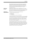
Ethernet Interface
Characteristics
The Ethernet interface has a 10BaseT interface complying with the IEEE 802.3
standard, and is terminated in an RJ-45 shielded connector, which can operate
over UTP and STP media.
V.35
768kbps
ASMI-450
HDSL Line
BRIDGE
BRIDGE
V.35
768kbps
LAN
LAN
ASMI-450
ASMI-450
HDSL Line
LOCAL
LAN
REMOTE
LAN
ASMI-450