


Front-Panel Operating Instructions
3-2 ASMi-450 Installation and Operation Manual
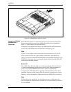
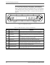
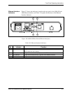
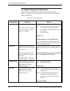
3.2 Front Panel Controls, Connectors, and Indicators
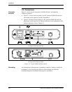
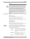
Figure 3-1 shows the front panel of the ASMi-450. Table 3-1 lists the functions
of the ASMi-450 controls, connectors and indicators, located on the ASMi-450
front panel. The index numbers in Table 3-1 correspond to the item numbers in
figure 3-1.
Figure 3-A. ASMi-450 Front Panel
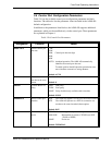
Table 3-A. ASMi-450 Controls, Connectors and Indicators
No. Control or Indicator Function
1 TD indicator Lights to indicate activity on the transmit line of the local DCE port.
2 RD indicator Lights to indicate activity on the receive line of the local DCE port.
3 LOS indicator Lights when the HDSL line circuits lose synchronization to the incoming
signal
4 QLTY indicator Lights when the far-end HDSL block error (FEBE) rate reported by the
remote equipment is less than 10
-7
(good quality)
5 ALM indicator Lights when alarms are stored in the ASMi-450 alarm buffer
6 TST indicator Lights when a test is active
7 Alphanumeric display Liquid crystal display (LCD) used to display messages and status
information. The display contains 2 rows of 16 characters each
8 CURSOR push-button Used to move among the information fields
9 SCROLL push-button Used to scroll among the available options of the displayed functions
10 ENTER push-button Used to enter the changes made in the ASMi-450 operation, and initiate
operation under the new set-up