


Installation
2-10 ASMi-450 Installation and Operation Manual
first the interface adapter cable to the RS-530
connector, then connect the user's data cable to the
37-pin D-type male connector at the other end of the
adapter cable.
Ethernet Interface The Ethernet interface has an RJ-45 connector for
direct connection to Ethernet 10BaseT LAN's.
Connector pin allocations and adapter cable wiring data appear in Appendix A.
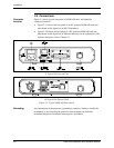
HDSL Line
Connections
The HDSL lines connect to the RJ-48C connector designated NETWORK
HDSL.
Control Port
Connection
Connect a cable prepared in accordance with Appendix A between the control
port connector, designated CONTROL DCE, and the control terminal. If the
control terminal is connected via modems, use a cross-over cable.
Note
The various user interface cables should be shielded, in order to comply with
FCC rules. The ASMi-450 and its data interfaces will work well even if the
cables are not shielded, but some radio interference may occur.