


( 16 / 80 )
IMPORTANT
Note on Differences between the Actual MCU and Emulator:
•Operations of the emulator system differ from those of actual MCUs as listed below.
(1) Reset condition
Set the time for starting up (0.2 Vcc to 0.8 Vcc) 1 µs or less.
(2) Initial values of internal resource data of an MCU at power-on
(3) Interrupt stack pointer (ISP) after a reset is released
(4) Capacities of the internal memories (ROM and RAM)
The evaluation MCU of this product has RAM of 31 KB (00400h--07FFFh) and flash ROM
of 4 KB (0F000h--0FFFFh) and 384 KB (A0000h--FFFFFh).
(5) Oscillator circuit
In the oscillator circuit where an oscillator is connected between pins XIN and XOUT, oscillation
does not occur because a converter board is used between the evaluation MCU and the target
system. It is same for pins XCIN and XCOUT. For notes on when using the oscillator circuit on
the target system, refer to "3.1.3 Using the Oscillator Circuit on the Target System" (page 29).
(6) A-D conversion
The characteristics of the A-D converter differ from those of actual MCU because there are
a converter board and other devices between the evaluation MCU and the target system.
(7) Ports P0 to P5, P10
This product emulates some I/O ports (P0 to P5, P10). Therefore, the electrical characteristics
of these ports differ from those of an actual MCU.
(8) Address and status of BHE*
When the internal RAM or ROM area of an MCU is accessed during user program execution,
actual MCUs retain a preceding address and status of BHE*, while this product does not.
(9) Status of a data bus
In stop or wait mode, actual MCUs retain a preceding status of a data bus, while with this
product a data bus is floating.
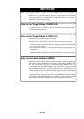
Note on the Watchdog Function:
• If the reset circuit of the target system has a watchdog timer, disable it when using the emulator.
Note on DMA Transfer:
•With this product, the program is stopped with a loop program to a specific address. Therefore, if
a DMA request is generated while the program is stopped, DMA transfer is executed. However,
make note that DMA transfer while the program is stopped may not be performed correctly. Also
note that the below registers have been changed to generate DMA transfer as explained here even
when the program is stopped.
(1) DMA0 transfer counter: TCR0
(2) DMA1 transfer counter: TCR1