


( 47 / 80 )
4.1.4 LED Display When the PC7501 Starts Up Normally
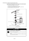
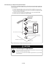
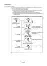
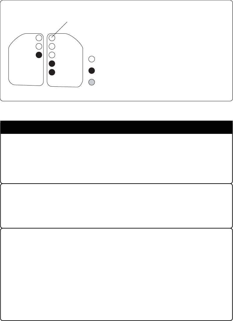
Figure 4.1 shows upper panel LED lighting status when the emulator started up properly. Check it
when starting up the emulator system.
Figure 4.1 LED display of the PC7501 when the power turned on
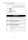
IMPORTANT
Note on Memory Expansion or Microprocessor Mode:
• To use the memory expansion or microprocessor mode, be sure to set pins RDY* and
HOLD* so that they are not active at startup. Otherwise the emulator system will not
start up correctly.
Note on the Target Status POWER LED:
• If your MCU has two or more Vcc terminals, the LED does not light unless power
is supplied to all the terminals.
• If this LED does not light, check the voltage of the target system.
• Check that power is supplied to all the power terminals.
• When the target system is not connected, this LED does not light.
POWER
CLOCK
RUN
RESET
WARNING
TARGET
STATUS
SYSTEM
STATUS
POWER
SAFE
ERROR
: ON
: OFF
: Flashing
Note on the Target Status CLOCK LED:
• If the LED is not turned on, check the following.
(1) After powering on the PC7501 (before starting up the emulator debugger):
Make sure that the oscillator circuit board is properly installed in the PC7501 and
it is oscillating normally.
(2) After the emulator debugger is started up (after the Init dialog box settings are
completed):
Make sure that the oscillator selected in the Init dialog box is oscillating normally.