


( 63 / 80 )
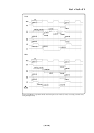
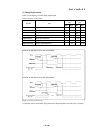
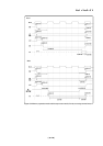
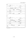
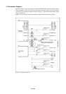
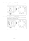
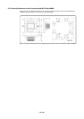
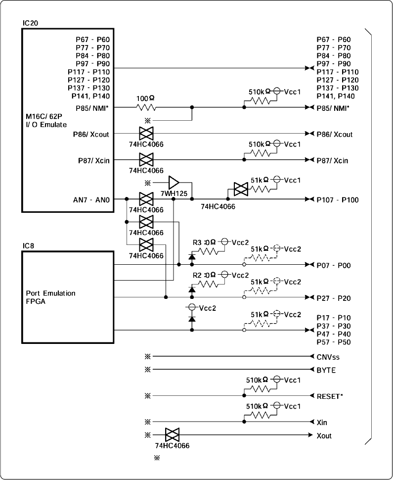
Figure 5.7 Connection diagram
5.4 Connection Diagram
Figures 5.7 shows a connection diagram of the M3062PT-EPB. This connection diagram mainly
shows the interface section. The circuits not connected to the target system such as the emulator's
control system are omitted. The signals not shown in Figure 5.7 connect the evaluation MCU and the
target system directly.
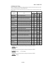
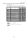
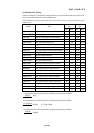
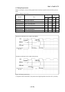
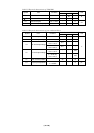
Tables 5.8 and 5.9 show IC electric characteristics of this product for reference purposes.
: Connected to emulator
Pullup resistors indicated by
dashed lines: socket mounted
Target system