


( 42 / 80 )
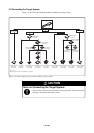
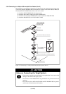
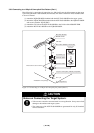
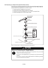
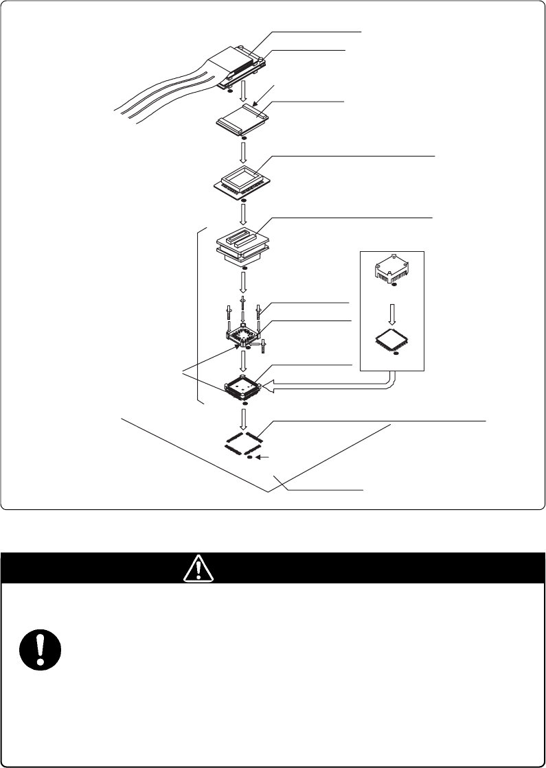
3.6.8 Connecting to a 100-pin 0.5-mm-pitch Foot Pattern (Part 3)
Here following is a procedure of connecting to a 100-pin 0.5-mm-pitch foot pattern on the target
system using the M3T-FLX-100NSD (not included). For details on the M3T-100LCC-DMS (not
included) and M3T-FLX-100NSD, refer to each user's manual.
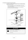
(1) Attach the M3T-FLX-100NSD to the target system.
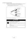
(2) Attach the M3T-100LCC-DMS to the M3T-FLX-100NSD.
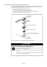
(3) Attach the CN2 side of the M30800T-PTC to the J4 side of the M3062PT-EPB.
(4) Attach the M30800T-PTC to the M3T-100LCC-DMS.
Figure 3.19 Connecting to a 100-pin 0.5-mm-pitch foot pattern (Part 3)
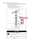
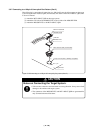
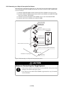
CAUTION
Notes on Connecting the Target System:
•Take care not to attach a converter board in a wrong direction. It may cause a fatal
damage to the emulator and targets system.
• The connectors of the M30800T-PTC are guaranteed for only 50 insertion/removal
iterations.
• The connectors of the M3T-100LCC-DMS and M3T-FLX-100NSD are guaranteed
for only 20 insertion/removal iterations.
M3062PT-EPB
M30800T-PTC
100-pin 0.5-mm-pitch (100P6Q) foot pattern
M3T-100LCC-DMS (not included)
M3T-FLX-100NSD (not included)
YQ-GUIDE (x4)
NQPACK100SD
YQPACK100SD
These corners are not round.
*
Target board
No. 1 pin
CN2 side
M3T-FLX160-EPB
HQPACK100SD
(not included)
MCU with flash
ROM etc.
Evaluation with
actual MCU
(1)
(2)
(4)
(3)
* Available in one package