


( 30 / 80 )
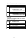
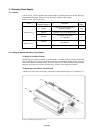
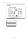
3.2 Switch Settings
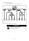
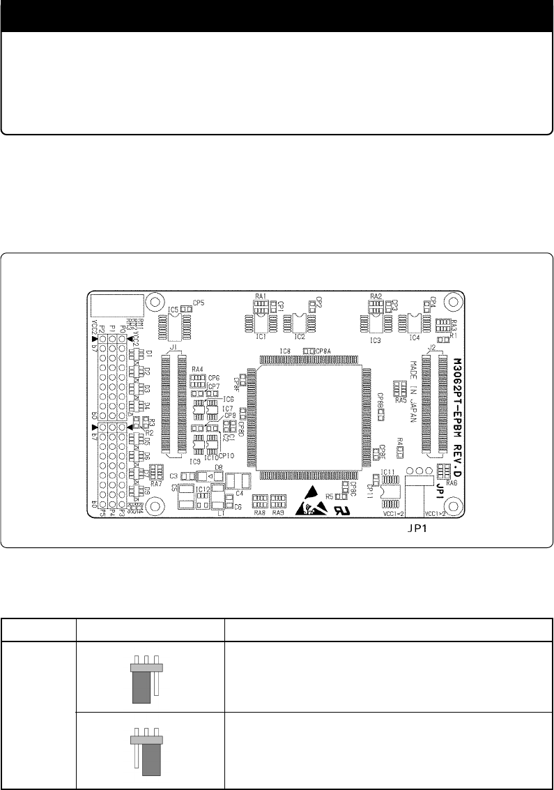
Set jumper switch JP1 according to a power supply you use. Figure 3.7 shows the positions of jumper
switch JP1. Table 3.2 lists how to set the switch.
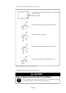
Figure 3.7 Position of the JP1
Table 3.2 Switch settings of the JP1
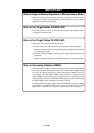
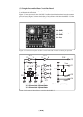
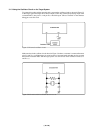
3.1.4 Using the Internal Generator Circuit
The dedicated circuit in the PC7501 can generate any arbitrary frequency specified by the emulator
debugger, and it can be supplied as a main clock. It does not depend on either the oscillator circuit
board in the PC7501 or the oscillator circuit on the target system. If you want to debug programs
without the target system or change a frequency temporarily, you can check its operation before
purchasing an oscillator. If you want to use the internal generator circuit in the PC7501 as a main
clock, choose "Generate" in the emulator debugger and specify a frequency you like to use this clock.
Although you can change a frequency between 1.0 and 99.9 MHz by 0.1 MHz for the PC7501, do
not specify a value exceeding the maximum input frequency of the XIN of an MCU.
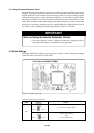
IMPORTANT
Note on Using the Internal Generator Circuit:
• The internal generator circuit is equipped for temporary debugging purposes.
Temperature characteristics of frequencies are not guaranteed.
JP1
2.7 V ≤ Vcc1 = Vcc2 ≤ 5.5 V
4.8 V ≤ Vcc1 ≤ 5.2 V
and
2.7 V ≤ Vcc2 < Vcc1
(Factory-setting)
VCC1 = 2 VCC1 > 2
VCC1 = 2 VCC1 > 2
Switch Setting Voltage
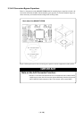
Front side of the M3062PT-EPBM