


Installing the IEEE 1284 Parallel Type305
17
2
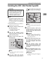
Installing the IEEE 1284 Parallel Type305
R
CAUTION:
Note
❒
The parallel interface board can be
attached to either the left or the
right side of the back of your print-
er. This procedure is for attaching
to the left side.
❒
You cannot install two parallel in-
terface boards at a time.
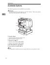
A Check the contents of the box for
the following items.
• Parallel interface board
• Installation Guide
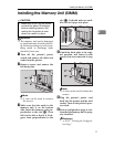
B Turn off the printer's power
switch and remove all cables and
cords from the printer.
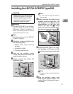
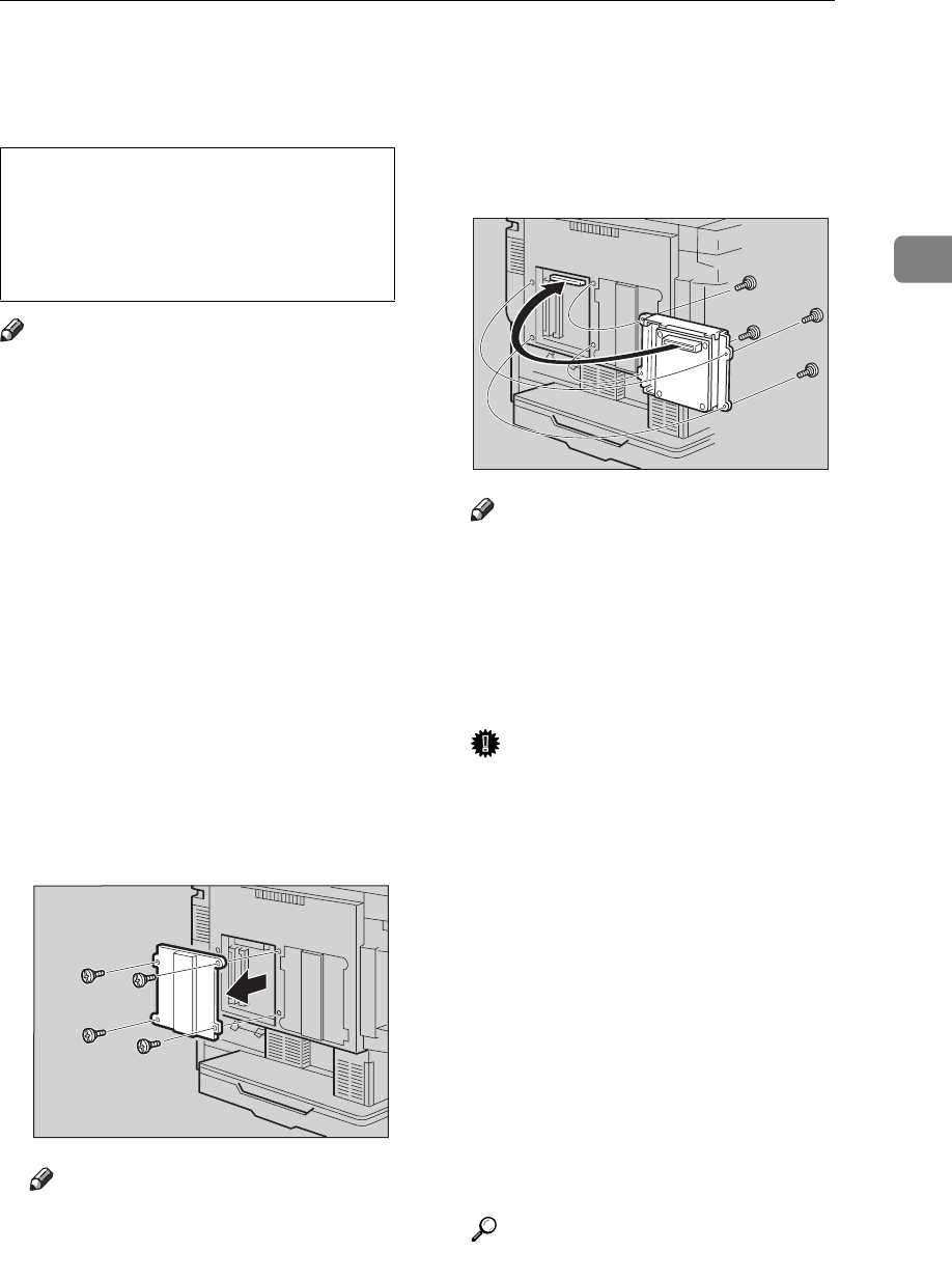
C Remove screws and remove the
left back plate.
Note
❒
A coin can be used to remove
the screws.
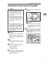
D Insert the IEEE 1284 Parallel
Type305 into the slot and fasten it
with screws that were removed in
step C
CC
C, as shown in the illustra-
tion.
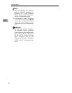
Note
❒
A coin can be used to fasten the
screws.
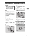
E Attach the interface cable to the
parallel interface connector of the
printer. Secure the cable with the
metal fittings.
Important
❒
Rating voltage of the parallel in-
terface connector for the com-
puter; Max. DC 5V.
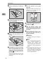
F Attach the other end of the inter-
face cable to the interface connec-
tor of the computer, and secure
the cable.
G Plug the printer's power cord
back into the printer and the wall
socket. Turn on the printer's pow-
er switch.
H Print a configuration page to con-
firm that parallel interface board
is properly installed.
Reference
⇒ P.107 “Printing the Configura-
tion Page”
•
Make sure to turn off the printer
and wait for about 30 minutes
before installing options. Not
waiting for the printer to cool
down can result in a burn.
TFWX185E
TFWP080E