


MODELS
ULTRAVIEW PRO INSTALLATION AND OPERATIONS MANUAL
5
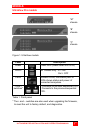
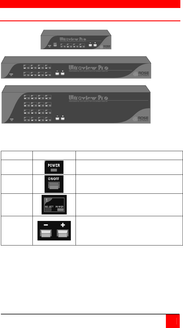
UltraView Pro models
“M”
chassis
“B”
chassis
“C”
chassis
Figure 1. UltraView models
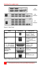
Label Description
Power
Power LED (Green when unit is on)
On/Off
“M” chassis only. In = ON
Out = OFF
LEDs
Indicator LEDs; Numbered pairs of
LEDs shows status and power of
connected computers.
+ And –
switches*
+ Connects to the next sequential CPU,
- Connects to the previous sequential
CPU.
Table 1. Front panel
* The + and – switches are also used when upgrading the firmware,
to reset the unit to factory default, and diagnostics.