


11
Part Names and Functions
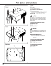
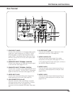
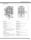
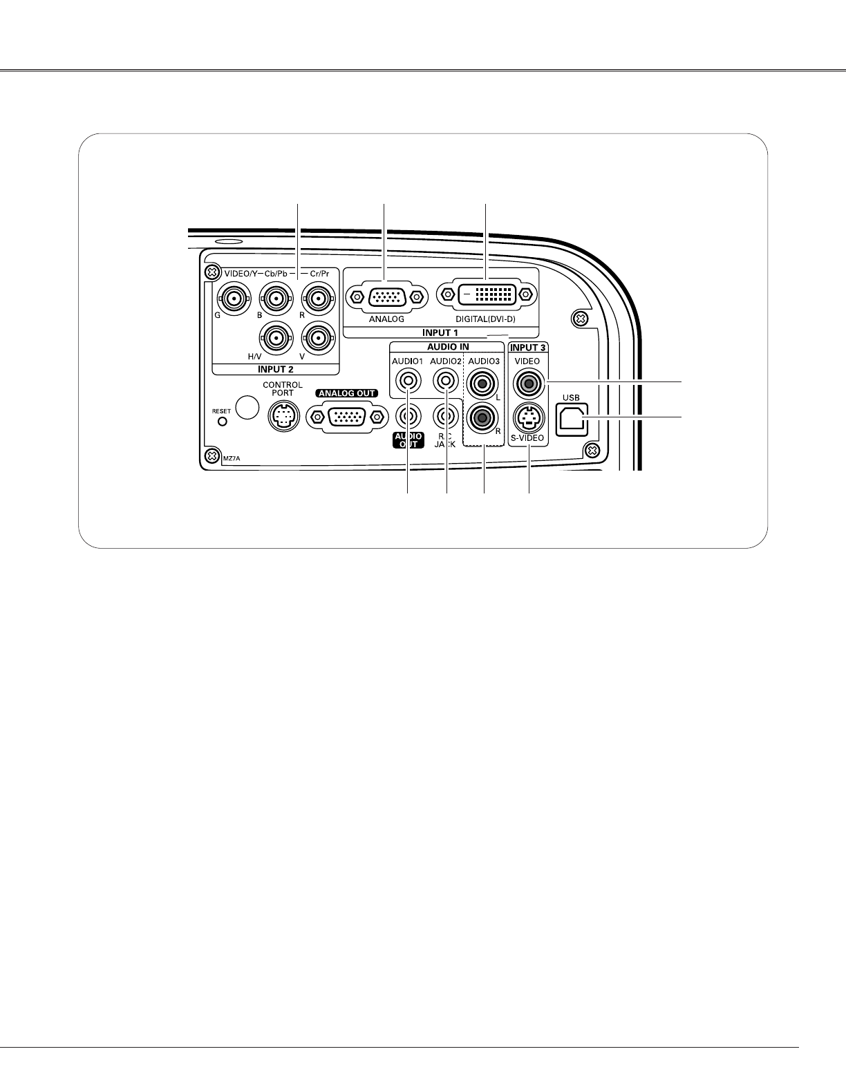
Rear Terminal
q w e
r
t
yi u
t USB CONNECTOR (Series B)
Use this connector when controlling a computer
with the remote control of the projector. Connect
the USB terminal of your computer to this
connector with the supplied USB cable. (See page
22.)
y S-VIDEO INPUT JACK
Connect the S-VIDEO output signal from video
equipment to this jack. (See page 23.)
i AUDIO 2 JACK
Connect the audio output (stereo) signal from a
computer or video equipment to this jack. (See
pages 22–24.)
o AUDIO 1 JACK
Connect the audio output (stereo) signal from a
computer or video equipment to this jack. (See
pages 22, 24.)
r VIDEO INPUT JACK
Connect the composite video output signal from
video equipment to this jack. (See page 23.)
u AUDIO 3 JACKS (L/R)
Connect the audio output signal from video
equipment to these jacks. (See page 23.) For a
mono audio signal (a single audio jack), connect to
the AUDIO-L (Mono) input jack.
q 5 BNC INPUT JACKS
Connect the component or composite video output
signal from video equipment to VIDEO/Y, Cb/Pb,
and Cr/Pr jacks or connect the computer output
signal (5 BNC Type [Green, Blue, Red, Horiz. Sync,
and Vert. Sync.]) to G, B, R, H/V, and V jacks. (See
pages 22, 24.)
w COMPUTER INPUT TERMINAL (ANALOG)
Connect the computer (or RGB scart) output signal
to this terminal. (See pages 22, 24.)
e COMPUTER INPUT TERMINAL (DIGITAL)
Connect the computer output signal (Digital DVI-D
type) to this terminal. The HD (HDCP compatible)
signal can also be connected. (See pages 22, 24.)
o