


Section 4. Cleaning and Maintenance
SATO M-84PRO PN 9001105 Rev. A Page 4-5
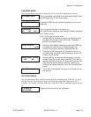
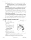
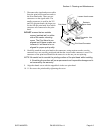
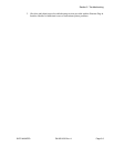
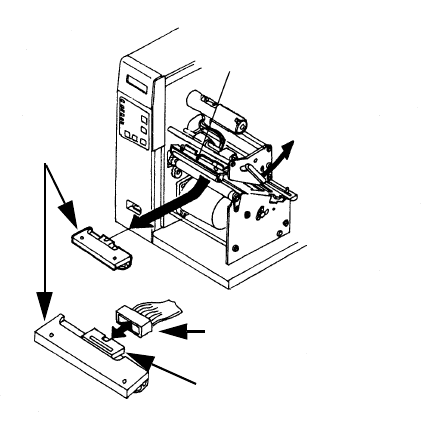
7. Disconnect the signal and power cables
from the print head connectors and set
the Print Head aside. There are two
connectors on the signal cable. The
smaller connector is used for the 203
and 305 dpi print heads, the larger one
for the 609 dpi print head. Note which
connector was connected to the print
head.
DO NOT remove the two outside
screws (painted red) on either
side of the center mounting
screw. The Print Head is pre-
aligned and if these screws are
lossened, it will have to be re-
aligned for proper print quality.
8. Carefully attach the new print head to the connectors, using caution to make sure the
connector keys are correctly positioned and that the correct cable connector is used. The
connector on the print head should be the same size as the one you are replacing.
NOTE: Be careful not to scratch the printing surface of the print head while installing
it. Scratching the surface will cause permanent and irreparable damage and is
not covered by the warranty!
9. Align the thumb screw with the tapped hole in the new print head.
10. 11. Re-secure the print head by tightening the screw.
Loosen thumb screw
Rotate to
open head
Print Head
Print Head Connector
Signal Connector. Use
correct size.