


Introducing the BM85 Bridge/Multiplexers
31007492
5
1.2.3 Operating Power
AC/DC Models
These models are supplied with a power cable of 6 ft (2 m) length for
operation from 110-120 Vac or 220-240 Vac single-phase power. The
cable connects to a socket on the rear panel. Grounding is through the
cable. The BM85 contains an ac line fuse that is accessible to the user.
All of these models except the BM85-000 can also operate from an
external 24 Vdc source. Power connects to a socket on the rear panel.
Grounding is through the cable. The dc power source must be fused
externally to the BM85.
DC/DC Models
These models operate from a 125 Vdc or 24 Vdc source. Power connects
to a terminal strip on the rear panel. A grounding terminal is provided.
The dc power source must be fused externally to the BM85.
1.2.4 Configuration Methods
All BM85 models must be configured internally for your application
before you can connect them for operation in your application. This is
necessary because the BM85's internal configuration specifies how each
serial port will operate.
Each model has two sets of rear panel switches. One set assigns the
Modbus Plus node address. The other set allows you to either configure
the unit or set it into its RUN mode.
Configuring the Modbus Port Models
For the Modbus serial port models, you configure the unit locally at a
serial terminal connected to one of its ports.
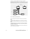
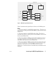
Configuring the Programmable Port Models
For the programmable models, you create an application program
externally to the BM85 and then download it to the unit across the
Modbus Plus network.
Setting the RUN Mode
When you have properly completed your configuration of the BM85, you
can set it into its RUN mode for operation in your application.
Caution:ąDo not connect the BM85 into your application
environment unless you have set its internal configuration.
Do not connect it to your network or to any device unless you
have set its switches properly for configuring or running.