


Configuring the Modbus Models
31007492
54
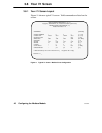
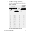
3.13 Modbus Port Indicator Codes
If the BM85 detects a condition that prevents communication at its
Modbus Plus or Modbus ports, it shuts off all ports and displays an error
code pattern at its four Modbus port indicators.
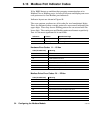
Indicator layouts are shown in Figure 22.
The error pattern produces two 4-bit codes for two hexadecimal digits.
First, the indicators show a steady pattern for one second, indicating the
upper digit. Then they show a flashing pattern for one second with the
lower digit. The continuous and flashing patterns alternate repetitively.
Port 4 is the most significant bit in each code.
Indicators Pattern Hexadecimal Digit
4 – 3 – 2 – 1 Steady Upper digit
4 – 3 – 2 – 1 Flashing Lower digit
Hardware Error Codes: 11 ... 19 Hex
Code (Hexadecimal) Meaning
11 PROM checksum error
12 RAM data test error
13 RAM address test error
14 Normal power down event
17 Bad or unexpected interrupt
18 EEPROM checksum error
19 Modbus port loopback error
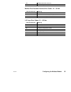
Modbus Driver Error Codes: 24 ... 2E Hex
Code (Hexadecimal) Meaning
24 Modbus transmit state error
25 Modbus receive state error
26 ASCII transmit communications state error
27 Transmit underflow error
28 RTU transmit communications state error
29 ASCII receive communications state error
2A RTU receive communications state error
2B Transmit communications state error
2C Receive communications state error