


Installing the BM85
31007492
76
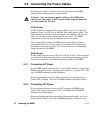
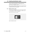
5.3 Connecting the Network and Serial Cables
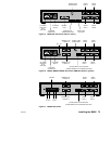
Network and serial cable connectors are located on the BM85 rear panel.
Rear panel views are provided in the following figures:
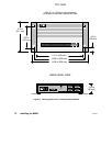
V Figure 19: BM85-000
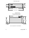
V Figure 20: BM85C, E, S
V Figure 21: BM85D
Read the Cautions below before connecting any cable to the BM85.
After connecting each cable, secure the connection by tightening its two
screws.
Caution:ąIf you are connecting the unit to the network for the
purpose of communicating in your application, you must first
ensure that you have set the unit's internal configuration for
the specific site at which you are installing the unit. If you
have not done this, you must first configure the unit as
described in this guidebook.
If you are connecting the unit to the network for the purpose
of downloading its configuration from your host computer, you
must set the unit's rear panel switches for downloading . You
must do this before connecting the network cables, and before
applying operating power to the unit.
Caution:ąIf the network is active, communication between the
devices on the network will be affected as you connect the
BM85 to the network. Before connecting any device on an
active network, you should know the affect of connecting that
device.
Caution:ąIf the cables at the installation site are not labeled,
or if you do not have a layout diagram showing how to connect
the cables, obtain that information before proceeding.