


Installing the BM85
31007492
70
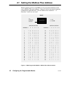
5.1 Installing the BM85 Hardware
5.1.1 Mounting the BM85
BM85 models are available for mounting on a horizontal shelf or vertical
panel, or for installation into a standard 19 inch rack. Install your unit
using the guidelines in Section 5.1.2 (for shelf or panel mounting) or
5.1.3 (for rack mounting).
The BM85 has a set of LED indicators to show its operating status. Your
choice of a mounting method should include proper access for observing
these indicators.
You should also provide access to the unit's rear panel for setting the
switches, connecting the cables, and servicing.
Caution:ąDo not connect the BM85 into your application
environment unless you have set its internal configuration.
Do not connect it to your network or to any device unless you
have set its switches properly for configuring or running.
See the Specifications Sections 1.6 and 1.7 for details about the BM85
operating power, environment, and connector requirements.
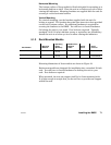
5.1.2 Shelf/Panel Mounted Models
Part Number
Mounting
Method
Operating
Power
(Nominal)
Modbus Plus
Network
Cable
Serial
Ports
Serial
Protocol
NW–BM85–000 Panel or Shelf 115/230 Vac Single Modbus ASCII or RTU
NW–BM85C002 Panel or Shelf 115/230 Vac or
24 Vdc
Single or Dual Modbus ASCII or RTU
NW–BM85E232 Panel or Shelf 115/230 Vac or
24 Vdc
Single or Dual RS232 Programmable,
User Defined
NW–BM85E485 Panel or Shelf 115/230 Vac or
24 Vdc
Single or Dual RS485 Programmable,
User Defined
NW–BM85S232 Panel or Shelf 115/230 Vac or
24 Vdc
Single or Dual RS232 Programmable,
User Defined
NW–BM85S485 Panel or Shelf 115/230 Vac or
24 Vdc
Single or Dual RS485 Programmable,
User Defined
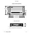
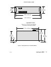
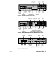
Mounting dimensions of these models are shown in Figure 17.