


Configuring the Modbus Models
31007492
40
3.5 Configuring the Modbus Ports
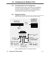
3.5.1 Connecting Power for the Configuration
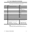
3.5.2 Setting the Switches
12345678
SWITCH POSITION
12345678
PORT MODE:
CONFIGURE
RUN
CONFIGURATION PORT:
PORT 1
PORT 2
PORT 3
PORT 4
PARITY:
DISABLED
EVEN
DISABLED
ODD
BAUD RATE:
9600
2400
1200
300
UP
UP
UP
DOWN
DOWN
DOWN
UP
UP
DOWN
DOWN
UP = 1 DOWN = 2
NW-BM85-000
(Pv02 or earlier)
NW-BM85C002
NW-BM85D008
NW-BM85-000
(PV03 or greater)
USE
UPPER
SWITCHES
USE
RIGHT
SWITCHES
NW-BM85-000 = ST OP BITS:
UP = RUN APPLICATION
NW-BM85C002
rEFENW-BM85D008 = MODE:
(LEAVE IN UP POSITION)
UP
UP
DOWN
DOWN
UP
UP
DOWN
DOWN
UP
UP
DOWN
DOWN
UP
UP
DOWN
DOWN
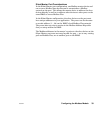
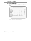
Figure 10 BM85 Modbus Models: Port Configuration Switches
Refer to the installation chapter in this guide for connecting power to
your BM85. Connect the source of AC or DC power to the BM85. Do
not turn on the power to the BM85 until you set the Modbus port
configuration switches and connect the configuration terminal. The
switch settings will be sensed when power is applied.
The BM85 power should be set off at this time. Switches are located on the
BM85 rear panel. Figure 10 shows the switch positions and setup.