


Installing the BM85
31007492
78
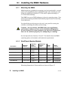
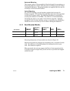
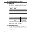
5.4 Reading the Indicators
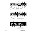
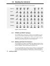
The layout of the BM85 indicators is shown below.
BM85–000:
BM85E232,
BM85S232:
BM85E485,
BM85S485:
BM85C:
BM85D002:
BM85D008:
Figure 22 Layout of the Indicators
5.4.1 POWER and READY Indicators
The POWER indicator illuminates steadily when the BM85 has power
from the source and its internal power supply is operating normally.
The READY indicator (BM85-000 only) illuminates steadily when the
BM85 has successfully completed its internal diagnostics.
5.4.2 Modbus and Serial Port Indicators
On the Modbus port models, each Modbus port indicator flashes when a
valid message is received at its port. If an internal fault exists, an error
pattern is flashed. These codes are listed in Section 3.13.
On the programmable port models, each port indicator is programmable
to show status that is specific to the application. Codes are flashed to
show status during downloading. These codes are listed in Section 4.8.