


Device Addressing and Message Routing
31007492
18
2.1 Modbus Plus Message Routing Paths
A single Modbus Plus network can have up to 64 addressable node
devices, with each device having a unique address of between 1 and 64.
Multiple networks can be joined through Bridge Plus devices. Devices
address each other across Bridge Plus devices by specifying routing
paths of five bytes, with each byte representing an address on the next
network. This routing method allows nodes in other networks to be
addressed up to four networks away from the originating node.
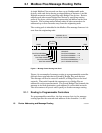
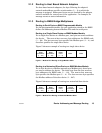
The routing path is imbedded in the Modbus Plus message frame as it is
sent from the originating node:
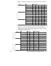
MESSAGE FRAME
ROUTING
PATH
ROUTING ADDRESS 1
ROUTING ADDRESS 2
ROUTING ADDRESS 3
ROUTING ADDRESS 4
ROUTING ADDRESS 5
MODBUS PLUS
EXAMPLE:
ROUTING ADDRESS 1 = 25
ROUTING ADDRESS 2 = 20
ROUTING ADDRESS 3 = 12
ROUTING ADDRESSES 4, 5 = 0
(NO FURTHER ROUTING)
START
END
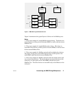
Figure 4 Message Frame Routing Path Field
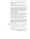
Figure 4 is an example of message routing to a programmable controller
through three networks that are joined by Bridge Plus node devices.
The message will first be routed to node 25, a Bridge Plus on the local
network. That node forwards the message on to a Bridge Plus at
address 20 on the second network. The second Bridge Plus forwards the
message to its final destination, node address 12 on the third network.
The zero contents of bytes 4 and 5 specify no further message routing.
2.1.1 Routing to Programmable Controllers
For programmable controllers, the last non-zero byte in the message
routing specifies the network node address of the controller (1 to 64).