


Installing the BM85
31007492
74
5.2 Connecting the Power Cables
See Sections 1.6 and 1.7 Specifications for details about the BM85
operating power and connector requirements.
Caution:ąYou can connect power cables to the BM85, but
ensure that the power is OFF before connecting the network
or serial cables to the unit.
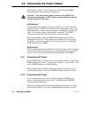
AC/DC Models
AC/DC models are supplied with a power cable of 6 ft (2 m) length for
operation from 110-120 Vac or 220-240 Vac single-phase power. The
cable connects to a socket on the rear panel. Grounding is through the
cable. The ac line switch is located on the rear panel. The BM85
contains an ac line fuse that is accessible on the rear panel.
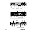
All of these models except the BM85-000 can also operate from an
external 24 Vdc source. Power connects to a socket on the rear panel.
Grounding is through the cable. The dc source must be switched and
fused externally to the BM85.
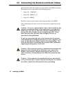
DC/DC Models
DC/DC models operate from a 125 Vdc or 24 Vdc source. Power connects
to a terminal strip on the rear panel. A grounding terminal is provided.
The dc source must be switched and fused externally to the BM85.
5.2.1 Connecting AC Power
Set the BM85 power switch to the `0' (power OFF) position. Connect the
BM85 to the power source. Set the power switch to `ā1ā' (power ON). The
unit's POWER indicator should illuminate.
Before connecting the network cables, set the power switch to the `0'
(power OFF) position. The unit's POWER indicator should not be lit.
5.2.2 Connecting DC Power
Set the external dc power source to OFF. Connect the BM85 to the
source. Set the dc power source to ON. The BM85 unit's POWER
indicator should illuminate.
Before proceeding with the connection of the network cables, set the dc
power source to OFF. The unit's POWER indicator should not be lit.