


Device Addressing and Message Routing
31007492
20
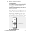
2.2 Modbus Address Conversion
Programmable Port Models
For the programmable models, the user application stored in the BM85
defines the addressing conventions to be used between the serial ports
and Modbus Plus. The application program must define the routing
between serial ports, as well as the paths to Modbus Plus nodes.
Modbus Port Models
For the Modbus port models, address conversion between Modbus and
Modbus Plus addresses is provided internally as described below.
Examples are shown in Section 2.3.
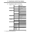
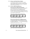
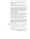
When the BM85 receives a message at a Modbus port, the Modbus
address (1 ... 255) is compared to an internal address map for that port.
You define the map table during your BM85 configuration. It can hold
up to 64 Modbus addresses, each pointing to a five-byte routing path.
If an address match is found in the table, the five routing path bytes are
applied to the message. If the first byte is in the range 1 ... 64, the
message is routed out on Modbus Plus. If the first byte is zero, the
message goes to a Modbus port (1 ... 4) specified in byte two. If that port
has a single slave device, the remaining three bytes are zeros. If the port
has a network of slave devices, byte three specifies the slave address.
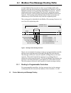
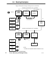
RESERVED
RESERVED
0
1
64
65
79
80
255
DIRECT
ATTACH
ADDRESS
MUX ATTACH
ADDRESS
IMPLICIT
ATTACH
ADDRESS
70
71
74
75
RESERVED
NOTE:
ALL ADDRESSES 65 ... 79
ARE RESERVED AT ANY
PORT CONFIGURED IN THE
‘SILENT MASTER’ MODE.
Figure 7 Bridge Multiplexer Address Conversion