


Configuring the Modbus Models
31007492
36
3.4.8 Modbus Address Map
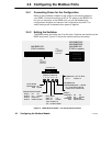
The BM85 maintains four internal Modbus Address Map tables for
routing the Modbus messages received at its four Modbus ports. Each
port has a table that can hold up to 64 entries that you specify during
configuration.
V the location in the table at which you want to place the entry
V a one-byte Modbus address in the range 1 ... 255 decimal
V a five-byte routing path.
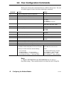
Each table entry specifies how you will want a Modbus address received
at the Modbus port to be converted into a five-byte routing path to the
destination device in your application. Routing can be made to a
Modbus Plus node on the local network or on a remote network.
Messages can also be routed to a device on another port of the BM85.
When a Modbus message is originated from a device at one of its Modbus
ports, the BM85 searches the Modbus Address Map table for that port to
find a match between the message's Modbus address and a Modbus
address stored in the table. The actions taken if a match is found, or if a
match is not found, are described below and on the following pages.
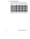
If a Match is Found
If a match is found, the five bytes of mapped routing from the table
entry will be applied to the message, and it will be sent out using that
routing. Here are five examples of how the Modbus Address Map table
can be used to develop routing paths for Modbus messages:
Table Location Modbus Address Five–Byte Routing Path
01 47 8 0 0 0 0
02 182 20 14 0 0 0
03 27 20 22 5 0 0
04 33 0 3 0 0 0
05 125 0 4 99 0 0
V Entry 01 is an example of routing to node 8 on the local
Modbus Plus network. If the Modbus message contains the
destination address 47, a match is found in the table. The BM85
will apply the routing path 8, 0, 0, 0, 0 to the message. The
message is acted upon by the application program in the device at
node address 8.