


Configuring the Modbus Models
31007492
37
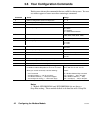
V Entry 02 is an example of routing through a Bridge Plus to a
programmable controller at node address 14 on a second network.
Finding a match for Modbus address 182, the BM85 applies the
routing path 20, 14, 0, 0, 0 to the message. It will be sent to node
20 on the current Modbus Plus network, a Bridge Plus. It will be
routed through the bridge to node 14 on the second network.
V Entry 03 shows how the type of device at the destination can
determine the routing of a message. Finding a match for Modbus
address 27, the BM85 applies the routing path 20, 22, 5, 0, 0 to the
message. The message is sent to node 20 on the current network,
a Bridge Plus. The message is routed through the bridge to node
22 on the next network. The type of device at node 22 determines
how further routing is applied. If node 22 is another Bridge Plus,
the message is routed to node 5 on a third network. āIf node 22 is
an SA85 or SM85 Network Adapter, the message is accepted by the
adapter and posted to application task 5 running in the adapter.
V Entry 04 shows routing to a single slave device on another port of
the same BM85. Finding a match for Modbus address 33, the
BM85 will apply the routing path 0, 3, 0, 0, 0 to the message. The
zero in the first byte specifies internal routing to another Modbus
port. The second byte specifies port 3. Port 3 must have only a
single slave device connected, as the remaining bytes are zeros.
V Entry 05 shows routing to a networked slave device on another
port of the same BM85. If the Modbus message contains an
address of 125, the routing path 0, 4, 99, 0, 0 is applied. The zero
in the first byte specifies internal routing to another Modbus port.
The second byte specifies port 4. The third byte specifies slave
device address 99 on the network at that port. The remaining
bytes must contain zeros.
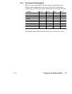
If a Match is Not Found
If an address match is not found in the table, the Modbus address in the
message will be converted by the BM85 into a routing path using the
methods described below. The resulting path can be either to the
Modbus Plus network, or to a single slave device connected to another
Modbus port of the Bridge Multiplexer.
V Address Range 1 ... 64 If the message contains an address in the
range 1 ... 64 decimal, it will be sent to the Modbus Plus node at
that address on the local Modbus Plus network.
For example, if the message contains Modbus address 8, it will be
sent to the Modbus Plus device at node 8.