


Configuring the Modbus Models
31007492
48
3.9 Your V2 and V3 Screens
3.9.1 Your V2 or V3 Screen Layout
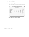
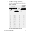
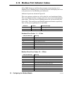
The V2 screen sets up Modbus Address Map table entries 1 ... 32 for the
currently selected port. The V3 screen sets up the table entries 33 ... 64.
Except for their table entries, the two screens are identical.
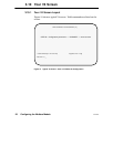
Figure 12 shows a typical V2 screen. Valid commands are listed on the
screen.
MODBUS ADDRESS MAP FOR [E1–E32] [V2]
MAPS: Modbus Address to Destination Address [Port Type: Master]
Table Modbus Destination Address Table Modbus Destination Address
Entry Address (5 bytes) Entry Address (5 bytes)
<E1 > [020]= 021 022 023 024 025 <E17> [000]= 000 000 000 000 000
<E2 > [000]= 000 000 000 000 000 <E18> [000]= 000 000 000 000 000
<E3 > [000]= 000 000 000 000 000 <E19> [000]= 000 000 000 000 000
<E4 > [124]= 020 004 000 000 000 <E20> [000]= 000 000 000 000 000
<E5 > [000]= 000 000 000 000 000 <E21> [000]= 000 000 000 000 000
<E6 > [126]= 020 006 000 000 000 <E22> [000]= 000 000 000 000 000
<E7 > [000]= 000 000 000 000 000 <E23> [000]= 000 000 000 000 000
<E8 > [000]= 000 000 000 000 000 <E24> [000]= 000 000 000 000 000
<E9 > [000]= 000 000 000 000 000 <E25> [000]= 000 000 000 000 000
<E10> [000]= 000 000 000 000 000 <E26> [000]= 000 000 000 000 000
<E11> [000]= 000 000 000 000 000 <E26> [000]= 000 000 000 000 000
<E12> [000]= 000 000 000 000 000 <E28> [000]= 000 000 000 000 000
<E13> [000]= 000 000 000 000 000 <E29> [000]= 000 000 000 000 000
<E14> [000]= 000 000 000 000 000 <E30> [000]= 000 000 000 000 000
<E15> [000]= 000 000 000 000 000 <E31> [000]= 000 000 000 000 000
<E16> [000]= 000 000 000 000 000 <E32> [000]= 000 000 000 000 000
>>Valid Commands:[V1 V2 V3 V4 P E] Keys:[Enter Esc ?–help]
Active Port 1>> __
Figure 12 Typical V2 Screen: Modbus Address Map Entries