


Compatible Devices and Cables
31007492
87
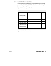
A.3 Modbus/RS232 Ports Pinout
This section covers the serial ports pinout for the following models:
Part Number
Mounting
Method
Operating
Power
(Nominal)
Modbus Plus
Network
Cable
Serial
Ports
Serial
Protocol
NW–BM85–000 Panel or Shelf 115/230 Vac Single Modbus ASCII or RTU
NW–BM85C002 Panel or Shelf 115/230 Vac or
24 Vdc
Single or Dual Modbus ASCII or RTU
NW–BM85D008 19 in Rack 125 Vdc or
24 Vdc
Single or Dual Modbus ASCII or RTU
NW–BM85E232 Panel or Shelf 115/230 Vac or
24 Vdc
Single or Dual RS232 Programmable,
User Defined
NW–BM85D002 19 in Rack 125 Vdc or
24 Vdc
Single or Dual RS232 Programmable,
User Defined
NW–BM85S232 Panel or Shelf 115/230 Vac or
24 Vdc
Single or Dual RS232 Programmable,
User Defined
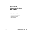
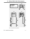
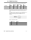
Figure 26 shows the pin configuration for the Modbus/RS232 port
connectors. If you are fabricating cables for your application, the panel
connector is a type DB9S.
54321
9876
REAR PANEL
SERIAL PORT
CONNECTORS
Figure 26 Serial Ports Pinout – Modbus/RS232
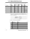
Pin BM85 Direction
Purpose
1 –– Chassis ground
2 In Receive data
3 Out Transmit data
4 Out Data Terminal Ready
5 –– Signal ground
6 In Data Set Ready
7 Out Request To Send
8 In Clear To Send
9 –– not used