


Configuring the Modbus Models
31007492
26
3.1 Before You Start
3.1.1 Models Covered in This Chapter
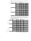
This chapter covers the configuration process for the following models:
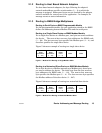
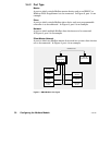
Part Number
Mounting
Method
Operating
Power
(Nominal)
Modbus Plus
Network
Cable
Serial
Ports
Serial
Protocol
NW–BM85–000 Panel or Shelf 115/230 Vac Single Modbus ASCII or RTU
NW–BM85C002 Panel or Shelf 115/230 Vac or
24 Vdc
Single or Dual Modbus ASCII or RTU
NW–BM85D008 19 in Rack 125 Vdc or
24 Vdc
Single or Dual Modbus ASCII or RTU
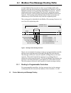
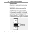
3.1.2 An Overview of the Configuration Process
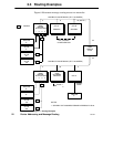
The BM85 requires the setup of internal configuration parameters for
each port that you will use in your application. The unit contains a
nonĆvolatile memory that stores the port configurations, even when
operating power is removed.
You must set the port configurations using a serial terminal (or a PC
with a terminal emulation program) connected to one of the BM85 ports.
The BM85 does not have to be connected to the Modbus Plus network.
A switch is provided on the BM85 to enable the unit to be configured.
If the unit is already installed at its site, you can configure it there.
You can also do the configuration prior to installing the unit at its site,
then transport the configured unit to the site and install it.
You must also set the Modbus Plus node address into a set of switches on
the BM85 rear panel.
Caution:ąYou must complete the internal configuration of the
BM85 before making the unit active in your application, both
on the Modbus Plus network and at its serial ports.
If you are installing a BM85 that was previously configured for
another application, another network, or a different node, the
unit will still be retaining its previous configuration setup.
You must not connect the unit into the current application and
apply operating power to the unit until you have reconfigured
it for the current application.