1-1
ROUTING SWITCHER SYSTEM (E)
Section 1
System Overview
1-1. Digital Routing Switcher System
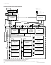
The system consists of the following units.
. Routing Switcher
(DVS-V1616/V3232B/V6464B/A3232/TC3232/RS1616, BVS-V3232/A3232, HDS-V3232)
It switches signals according to the command from the remote control unit. Varied switchers are
available for different types of signals used (serial digital video, digital audio, time code, RS-422A,
etc.)
. Remote Control Unit
(BKS-R1601/R3202/R3203/R3204/R3205/R3206/R1607/R1608/R3209/R3210/R3216/R1617/R3219/
R3280/R3281)
It switches signals and displays the name of the selected signal.
. Control Terminal
It sets the configuration and operation of the router system. It monitors the system in operation and
displays the messages.
A unique control protocol called S-BUS (Sony serial bus) is used for controlling the switcher system.
With this protocol, all control signals are transmitted by using one 75 Z coaxial cable. The transmission
path is called the “S-BUS data link”. Units on the S-BUS data links transmit data through time-divided
bi-directional communication.
Other than the S-BUS, the 9-pin remote control for RS-422A can also be used for this system. But the
system will function best when the S-BUS control is used. For DVS-V3232B/V6464B and HDS-V3232,
both protocols can be used together.
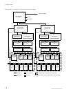
With cascade connection, several sets of routing switchers of DVS-V6464B/V6464M can be connected
together to expand the input/output matrix size. The inputs and outputs of DVS-V6464M can be expand-
ed up to 1024.
To operate this system, specified settings (making of table data) must be previously carried out using the
control terminal.


