


2-11
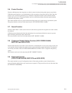
ROUTING SWITCHER SYSTEM (E)
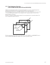
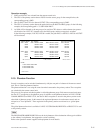
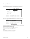
SOURCE GROUPS
NET GROUPS
DESTINATION GROUPS
S001:IN003 N001:OUT003-IN200 N002:OUT013-IN054 D001:OUT023
IN004 OUT004-IN201 OUT014-IN055 OUT024
IN005 OUT005-IN202 OUT015-IN056 OUT025
IN006 OUT006-IN203 OUT016-IN057 OUT026
S002:IN010 N003:OUT023-IN007 N004:OUT033-IN230 D002:OUT027
IN015 OUT024-IN008 OUT034-IN231 OUT028
IN023 OUT025-IN009 OUT035-IN233 OUT029
IN027 OUT026-IN010 OUT036-IN234 OUT030
: : :
( 20 groups ) ( 40 groups ) ( 20 groups )
PATHS
1:S001-N001-N002-D001
2:S002-N003-D001
3:S002-N004-D002
:
( 20 paths )
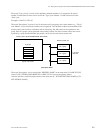
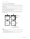
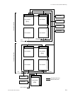
2-14. Tie Line Management (DVS-V3232B/V6464B, BKPF-R70 and HDS-V3232)
Operation example:
1. IN023 and OUT027 are selected from the remote control unit.
2. The CPU of the primary station detects IN023 from the source group. In the example below, the
corresponding group is S002.
3. Like for IN023, the CPU also detects OUT027. The corresponding group is D002.
4. The CPU of a primary station detects the path which has the S002 and D002 groups. In the following
example, the corresponding path is “3: S002-N004-D002”.
5. As N004 will be detected as the net group to be used, the CPU selects a usable element (not protect-
ed) from the four “OUT-IN” elements set in the N004 group, and the crosspoint is switched.
In the following example, if OUT033-IN230 is usable, the path IN023→OUT033→IN230→OUT027
will be selected.
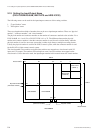
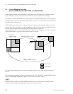
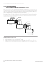
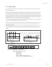
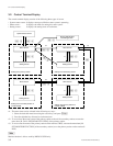
2-15. Phantom Function
Several crosspoints can be switched simultaneously with just one push of a button of the remote control
unit. This is called the phantom function.
The phantom function is set using the control terminal connected to the primary station. The crosspoints
are switched by the remote control unit.
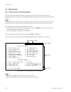
The group of crosspoints switched together is called the phantom group. Each remote control unit stores
the data of 57 crosspoints as the phantom group. In addition to the phantom function, in DVS-V3232B/
V6464B, BKPF-R70 or HDS-V3232, the data of 4095 crosspoints is stored in the primary station as the
other kind of phantom groups. In this manual, the registered phantoms in each remote control unit are
referred to as “local phantom”. Those registered in the primary station are referred to as “global phan-
tom”.
The global phantom function is available if a DVS-V3232B/V6464B, BKPF-R70 or HDS-V3232 is used
as the primary station.
n
The BKS-R1607/R1608/R3209/R3210 have the local phantoms of the destination offset type in addition
to the ordinary local phantom, that support the various switching.
Refer to the operation manual supplied with equipment for more details.