5-46
ROUTING SWITCHER SYSTEM (E)
5-2. Setting Items of the Secondary Station
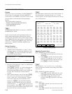
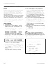
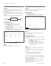
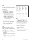
SWITCHING FIELD HDS-V3232 V2.10 STATION NUMBER 1
SWITCHING FIELD FIELD
F2:FIELD S:Table Set Ctrl-E:RETURN TO MENU
Z : SWITCHING FIELD (HDS-V3232 only)
Purpose
This menu is used to set the crosspoint switching field of
HDS-V3232 with the control terminal.
Setting Procedure
1. Select the menu item [Z].
2. Press [Ctrl] _ [E] to stop the display and the menu
screen of the secondary station will be displayed.
Example of Setting Screen
n
Unless pressing [S], the data will be deleted when the
power is turned off.
Operating Function Key
[F2] : FIELD (Mode which sets the crosspoint switching
field)
1. Press [F2]. The cursor will move to “SWITCH
ING FIELD” in the menu.
2. Press [Enter]. The setting will change.
(ODD → EVEN → FIELD → ASYNC → ODD)
All switching field in the switcher are deter
mined by this setting.
n
To use RS-422A and S-BUS together, set the switching
field as follows.
1 When using the S-BUS and CART protocol together :
ODD
2 When using the S-BUS and PRODUCTION
SWITCHER protocol together : FIELD
Note that the switching timing of the CART will not be
accurate if the CART and PRODUCTION SWITCHERS
protocols are used together.
Switching timing is not guaranteed in the combination of
different switching fields.
For details of the signal switching timing, refer to “5-8.
Signal Switching Timing”.
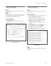
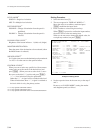
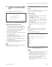
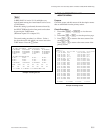
DVS-RS1616
EDITOR,
etc (M)
VTR,
etc (S)
(S) (M)
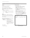
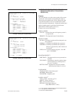
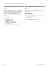
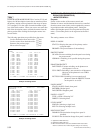
SELECT CONNECTION DVS-RS1616 V3.01 STATION NUMBER 5
OUTPUT (INPUT) INPUT
TERMINAL:DIRECTION TERMINAL:DIRECTION TERMINAL:DIRECTION TERMINAL:DIRECTION
01(17): M 09(25): M 01 : S 09 : S
02(18): M 10(26): M 02 : S 10 : S
03(19): M 11(27): M 03 : S 11 : S
: :
: :
08(24): M 16(32): M 08 : S 16 : S
S:TABLE SET
Ctrl-E:RETURN TO MENU
Z : SELECT CONNECTION (DVS-RS1616 only)
Purpose
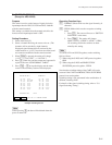
As for DVS-RS1616, this menu is used to set, “M”
(controlling side) or “S” (controlled side) for each 9-pin
connector from 1 to 32.
If a controller is connected to a 9-pin connector, set to (S).
If a controlled device is connected to a 9-pin connector, set
to (M).
When setting to (S), termination is automatically made.
Setting Procedure
1. Select the menu item [Z].
2. Select a input/output number using the cursor.
3. Press [Enter], the setting status changes.
(“M” → “S” → “M”)
4. Press [S] (TABLE SET), the content now appeared is
copied to the table data.
5. Press [Ctrl] _ [E] to stop the display and the menu
screen of the secondary station will be displayed.
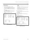
Example of Setting Screen
n
Unless pressing [S], the setting will be ignore.


