


5-16
ROUTING SWITCHER SYSTEM (E)
5-1. Setting Items of the Primary Station
SET TIE LINES DVS-V6464B V2.10 STATION NUMBER 1
SOURCE GROUPS
S001: 010(OUT010 ) S002: ...(.......) S003: ...(.......) S004: ...(.......)
011(OUT011 ) ...(.......) ...(.......) ...(.......)
012(OUT012 ) ...(.......) ...(.......) ...(.......)
013(OUT013 ) ...(.......) ...(.......) ...(.......)
S005: ...(....... ) S006: ...(.......) S007: ...(.......) S008: ...(.......)
...(....... ) ...(.......) ...(.......) ...(.......)
...(....... ) ...(.......) ...(.......) ...(.......)
...(....... ) ...(.......) ...(.......) ...(.......)
===================================================================
P01:S -N -N -D P02:S -N -N -D
P03:S -N -N -D P04:S -N -N -D
P05:S -N -N -D P06:S -N -N -D
P07:S -N -N -D P08:S -N -N -D
P09:S -N -N -D P10:S -N -N -D
P11:S -N -N -D P12:S -N -N -D
P13:S -N -N -D P14:S -N -N -D
P15:S -N -N -D P16:S -N -N -D
P17:S -N -N -D P18:S -N -N -D
P19:S -N -N -D P20:S -N -N -D
F1:MOVE F2:JUMP F3:PgUp F4:PgDn F5:GROUP Ctrl-E:RETURN TO MENU
SET TIE LINES DVS-V6464B V2.10 STATION NUMBER 1
NET GROUPS
N001: LEVEL= 1 2 .... .... .... .... .... ....
020(OUT020 )> 021(IN021 ) 022(OUT022 )> 022(IN022 )
023(OUT023 )> 023(IN023 ) 024(OUT024 )> 024(IN024 )
N002: LEVEL= .... .... 3 4 .... .... .... ....
025(OUT025 )> 025(IN025 ) 026(OUT026 )> 026(IN026 )
027(OUT027 )> 027(IN027 ) 028(OUT028 )> 028(IN028 )
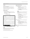
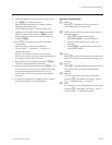
LEVEL: 1=VID 2=A1 3=A2 4=4 5=5 6=6 7=7 8=8
===================================================================
P01:S -N -N -D P02:S -N -N -D
P03:S -N -N -D P04:S -N -N -D
P05:S -N -N -D P06:S -N -N -D
P07:S -N -N -D P08:S -N -N -D
P09:S -N -N -D P10:S -N -N -D
P11:S -N -N -D P12:S -N -N -D
P13:S -N -N -D P14:S -N -N -D
P15:S -N -N -D P16:S -N -N -D
P17:S -N -N -D P18:S -N -N -D
P19:S -N -N -D P20:S -N -N -D
F1:MOVE F2:JUMP F3:PgUp F4:PgDn F5:GROUP Ctrl-E:RETURN TO MENU
SET TIE LINES DVS-V6464B V2.10 STATION NUMBER 1
SOURCE GROUPS
S001: ...(.......) S002: ...(.......) S003: ...(.......) S004: ...(.......)
...(.......) ...(.......) ...(.......) ...(.......)
...(.......) ...(.......) ...(.......) ...(.......)
...(.......) ...(.......) ...(.......) ...(.......)
S005: ...(.......) S006: ...(.......) S007: ...(.......) S008: ...(.......)
...(.......) ...(.......) ...(.......) ...(.......)
...(.......) ...(.......) ...(.......) ...(.......)
...(.......) ...(.......) ...(.......) ...(.......)
===================================================================
P01:S -N -N -D P02:S -N -N -D
P03:S -N -N -D P04:S -N -N -D
P05:S -N -N -D P06:S -N -N -D
P07:S -N -N -D P08:S -N -N -D
P09:S -N -N -D P10:S -N -N -D
P11:S -N -N -D P12:S -N -N -D
P13:S -N -N -D P14:S -N -N -D
P15:S -N -N -D P16:S -N -N -D
P17:S -N -N -D P18:S -N -N -D
P19:S -N -N -D P20:S -N -N -D
F1:MOVE F2:JUMP F3:PgUp F4:PgDn F5:GROUP Ctrl-E:RETURN TO MENU
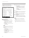
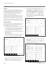
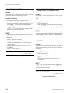
O: SET TIE LINES
Purpose
This menu is used to store the connection information of the
matrix in the primary station and to set the tie line for switching
several crosspoints using the remote control unit button.
Using this method, peripheral units such as the signal
converters can be used more efficiently.
The tie line consists of four input/output connectors as one
group and paths connected between sources and destina-
tions. The tie line system consists of a maximum of 20
groups for sources and destinations respectively, and a
maximum of 40 groups for connections, called Net groups.
Setting Procedure
Before you perform the tie line management using two or
three routing switchers, you should set the unit location
and the elements of the tie line as follows.
1. Set the offset of each unit on the menu screen [A : SET
UNIT LOCATION] of the secondary station in order
to avoid repeated input/output numbers of multiple
units and locate the units on one physical level.
2. Set the elements of the tie line on the menu screen [O :
SET TIE LINE].
Select menu item [O].
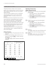
The top half of the screen is for setting the source group
while the bottom half is for setting the tie line path.
Example of Source Group Setting Screen
3. Select a source group number using the cursor and press
[Enter]. The source number input mode will be set.
Set the source name to the desired source group.
4. Input the source number using the numerical keys and
press [Enter] to set it. If [Ctrl] _ [F] is pressed
before the setting, the original source name will be
returned. When [Ctrl] _ [P] is pressed, the source
name will be deleted and “ · · · · ” will be displayed.
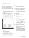
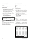
5. After setting the source group, press [F5]. The top
half of the screen will be switched to the destination
group setting screen.
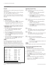
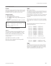
Example of Destination Group Setting Screen
6. Set the destination group in the same way as for the
source group.
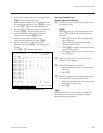
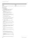
7. After setting the destination group, press [F5] and set
the net group setting screen.
Example of Net Group Setting Screen