


4-6
ROUTING SWITCHER SYSTEM (E)
4-4. Basic Setup Procedures
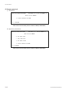
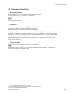
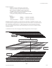
SOURCE/DEST/PHANTOM TYPE DVS-V6464B V2.10 STATION NUMBER 1
0=VTR 1=VCR 2=AUX 3=FLM 4=TEST 5=STU 6=CAM 7=REM
8=CG 9=NETA A=ENG B=ED C=FS D=SS E=BARS F=PHAN
Ctrl-E:RETURN TO MENU
(2) Assign Name Types (Menu Item [B])
Now select, and enter your 16 source and destination name pre-fixes.
Once again, up to 16 type names used for source/destination name are decided using 4 letters (except “;”).
Set using the menu item [B : SET SOURCE/DESTINATION TYPE].
Example : CAM, VTR, CG, DVE, MON, PGM, BLK, DAT, STL, TONE, CD, ...
If a consistent display format is desired, all name types should be the same length.
2. Source/Destination names (Menu Items [C] & [D])
At this point another very important decision must be made as to how your router system is organized,
programmed, and ultimately able to be used. You should take some time at this point to read, and totally
understand the implications of what this step in the setup means for future routing switcher setup, opera-
tion, and flexibility. How you approach this step will greatly determine the flexibility your system will
afford in control panel operation, and ease of system modification.
Many router systems are not only comprised of a SDI routing switcher (DVS-V**** routing switcher
frames), but additional types of routing switchers as well. If you only have DVS-V**** type SDI
routing switchers the information presented is not as critical to your operation, but should be read for
background information anyway. These additional routing switchers usually are analog audio, and/or
video routing switchers. Other possible routing switchers include AES/EBU, Analog Audio, Time Code,
and RS-422 machine control systems. These other routing switchers are usually controlled by the SDI
“primary” frame. This will be the case if you are using this guide for router system setup.
These additional types of routing switchers can be thought of as “assets” (secondary stations) to be
managed by the primary. These “assets” are additional crosspoints for switching analog video, or audio,
time code, etc. Your method for controlling these additional crosspoints are generally though control
panels attached to the S-BUS. Your mix of control panels, and the number, and type of additional, or
secondary routing switchers will determine the approach taken for “mapping” all the various crosspoints
in the primary, and secondary routing switchers.
There are two general approaches that can be taken in “mapping” crosspoints.
Although either approach can be mutually exclusive of the other, generally a mixture of the two are used.
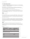
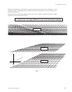
The first approach is called “level mapping”. There are sources where the digital (video), and analog
audio or video routing switchers should naturally follow one another (VTR’s for instance). With sources
that should follow, you can use “level mapping”, with the SDI routing switcher on level 1, and the audio
analog routing switcher on level 2, etc..
Looking at figure 1, VTR001 could have:
its SDI input connected to DVS-V*** routing switcher output 1,
and its AES/EBU audio input connected to DVS-A3232 routing switcher output 1,
and its analog audio input connected to analog audio routing switcher out 1.