


7-4
ROUTING SWITCHER SYSTEM (E)
SET TIE LINES DVS-128 V1.00 STATION NUMBER 1
--PATHS 1------------------------------------------------------------------
SOURCE: SOURCE No. DESTINETION No. ROUTE: SOURCE No. DESTINETION No.
L1 0001 - 0080 0001 - 0004 L2 0081 - 0082 0080 - 0086
DESTINATION:SOURCE No. DESTINETION No.
L1 0083 - 0089 0100 - 0130
--PATHS 2------------------------------------------------------------------
SOURCE: SOURCE No. DESTINETION No. ROUTE: SOURCE No. DESTINETION No.
L2 0001 - 0040 0005 - 0006 L. .... - .... .... - ....
DESTINATION:SOURCE No. DESTINETION No.
L1 0200 - 0201 0300 - 0400
--PATHS 3------------------------------------------------------------------
SOURCE: SOURCE No. DESTINETION No. ROUTE: SOURCE No. DESTINETION No.
L. .... - .... .... - .... L. .... - .... .... - ....
DESTINATION:SOURCE No. DESTINETION No.
L. .... - .... .... - ....
--PATHS 4------------------------------------------------------------------
SOURCE: SOURCE No. DESTINETION No. ROUTE: SOURCE No. DESTINETION No.
L. .... - .... .... - .... L. .... - .... .... - ....
DESTINATION:SOURCE No. DESTINETION No.
L. .... - .... .... - ....
F1:PgUp F2:PgDn Ctrl-E:RETURN TO MENU
7-2. Changed Menu (Primary Station Setting Items)
LEVEL TABLE DVS-128 V1.00 STATION NUMBER 1
LEVEL:1-16
1=VIT 2=A1 3=A2 4=TC 5=REM 6=B32 7=.... 8=....
9=.... 10=.... 11=.... 12=.... 13=.... 14=.... 15=.... 16=....
No. out VIT A1 A2 TC REM B32 .... ....
0001 OUT001 VIT A1 .... .... .... .... .... ....
0002 OUT002 VIT A1 .... .... .... .... .... ....
0003 OUT003 VIT A1 A2 TC REM B32 .... ....
0004 OUT004 VIT A1 A2 TC REM B32 .... ....
0005 OUT005 VIT A1 A2 TC REM B32 .... ....
0006 OUT006 VIT A1 A2 TC REM B32 .... ....
0007 OUT007 VIT A1 A2 TC REM B32 .... ....
0008 OUT008 VIT A1 A2 TC REM B32 .... ....
0009 OUT009 VIT A1 A2 TC REM B32 .... ....
0010 OUT010 VIT A1 A2 TC REM B32 .... ....
0011 OUT011 VIT A1 A2 TC REM B32 .... ....
0012 OUT012 VIT A1 A2 TC REM B32 .... ....
0013 OUT013 VIT A1 A2 TC REM B32 .... ....
0014 OUT014 VIT A1 A2 TC REM B32 .... ....
0015 OUT015 VIT A1 A2 TC REM B32 .... ....
0016 OUT016 VIT A1 A2 TC REM B32 .... ....
0017 OUT017 VIT A1 A2 TC REM B32 .... ....
F1:SEARCH F2:JUMP F3:LEVEL Ctrl-E:RETURN TO MENU
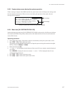
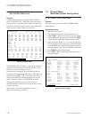
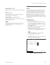
E : SET LEVEL TABLE
(DVS-128/HDS-X3000 Series)
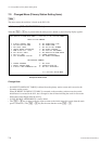
Purpose
The level name can be set, and the valid level for each
output terminal can be set.
Number of levels of either 8 or 16 can also be selected.
Example of Setting Screen
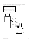
Every pressing of [F3:LEVEL] toggles between the
LEVEL: 1-8 display and the LEVEL: 1-16 display on the
2 nd line.
The LEVEL 9-16 is realized by switching the Destination
to which 512 is added, at the same time.
When the system is used with the LEVEL 1-16, the remote
control panel that supports the LEVEL 1-16 becomes
necessary.
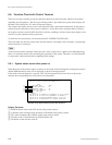
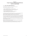
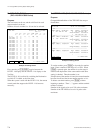
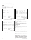
O : SET TIE LINES (DVS-128/HDS-X3000 Series)
Purpose
Change/addition/deletion of the TIE LINE data are per-
formed here.
Example of Setting Screen
To set the number, press [Enter] to be ready for number
input. Enter a number in the range of 1 to 1024. When
[Enter] is pressed again, the number is set, the range is
checked and duplication of the same number with other
setting is checked. Then the number is set.
If duplication of the number is found, the entered number
becomes invalid and the former number remains as it is.
To delete a terminal number, press [Enter] without
inputting a numbers. Then “....” appears and the terminal
number is deleted.
Number of the signals to be set is 254 at the maximum.
Number of the TIE LINEs to be set is 16 paths at the
maximum.